Iron Work
Description
This section is from the book "Text-Book Of Modern Carpentry", by Thomas William Silloway. Also available from Amazon: Text-book of Modern Carpentry.
Iron Work
The bolts used at the foot of principal rafters should not be less than five-eighths of an inch in diameter, nor more than an inch. For most purposes, three-fourths of an inch is best; and, when one of an inch in diameter is not sufficiently strong, it is better to increase the number than the size, and they should always be set at right angles with the rafters. The rods which support the beams must be of sufficient size to prevent vibration, but may vary in diameter according to the nature of the work, from five-eighths of an inch to two inches in diameter.
Great cafe should be exercised in the selection, using none but the very best material.
It is a common practice, in some instances, to use cast-iron boxings at the ends of principal rafters, and such other parts of a truss as will be subjected to great pressure, causing the fibres of the wood to indent each other. It is rare, however, that boxings are absolutely necessary.
Where a piece of framing is liable to be exposed to dampness before the work is put together, the iron should be heated to a blue heat, and well oiled over with the best quality of raw linseed oil. If this is properly done, the pores of the iron will be filled, and the metal effectually protected against corrosion.
Straps should be used sparingly, if at all; as the shrinkage of the wood leaves them loose, and the work is liable to settle. In most examples of old carpentry, these were freely used; but modern methods of framing with rods and bolts have obviated the necessity for them, so that they are now but rarely employed.
Plate VI
Fig. 3 of this plate exhibits a design for a roof of from forty to sixty feet span. Being very simple in its construction, it is more frequently used than any other. The trusses should be not more than eight or ten feet apart, and the common rafters twenty inches apart, from centres.
Table of dimensions, in inches, of limbers for roofs of various spans.
Names. | Span in Feet. | ||||
40 | 45 | 50 | 55 | 60 | |
Tie-beams .... | 6x8 | 7x8 | 8x9 | 8x10 | 9x11 |
Truss-rafters . . . | 6x7 | 7x7 | 8x8 | 8x9 | 9x9 |
Collar-beams . . . | 6x7 | 7x7 | 8x8 | 8x9 | 9x9 |
Common Kafters . . | 2x6 | 2x6 | 2x6 | 2x7 | 2x7 |
Purlins........ | 5x7 | 6x7 | 6x8 | 6x8 | 6x9 |
Struts........ | 3x6 | 4x7 | 4x8 | 5x8 | 5x9 |
Strengthening-pieces | 4x6 | 5x7 | 5x8 | 5x8 | 6x9 |
Rods...... | 1 in. | l 1/8in. | l 1/4 in. | l 1/2in. | 1 3/4 in. |
Bolts.......... | 3/4 in. | 3/4 in. | 7/8 in. | 1 in. | l 1/8 in. |
Fig. 1 exhibits in detail the framing at A, and Fig. 2 that at B.
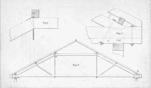
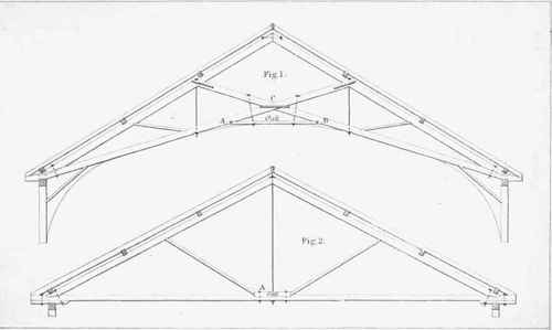
Plate VII
Fig. 2 exhibits a design for a roof of from thirty-five to fifty feet span. This roof, from its simplicity and strength, is, like that on Plate VL, much approved, and in common use.
Table of timber-dimensions for various spans.
Fig. 1 exhibits an example of a roof, with tie-beams, so framed as to admit of finishing a curved ceiling. The practice of thus dispensing with a horizontal or single tie-beam should be used with great caution, as the work is always liable to settle.
Table of timber-dimensions for various spans.
Names. | Span in Feet. | ||
40 | 45 | 50 | |
Tie-beams......... | 6X8 | 6X9 | 6X10 |
Truss-rafters........ | 6X7 | 6X8 | 6X9 |
Common Rafters....... | 2X6 | 2X6 | 2X6 |
Struts.......... | 2X6 | 3X6 | 4X6 |
Purlins......... | 5X7 | 6X7 | 6X8 |
Oak-piece........... | 4X6 | 5X6 | 6X6 |
Rods........... | 1 in. | l 1/8in. | 1 1/4 in. |
Bolts........... | 3/4 in. | 7/8 in. | 1 in. |
Names. | Span in Feet. | |||
35 | 40 | 45 | 50 | |
Tie-beams ............................................ | 6X7 | 6X8 | 7X9 | 8X9 |
Truss rafters .................................... | 6X6 | 6X7 | 7X8 | 8X8 |
Common Rafters .... | 2X6 | 2X6 | 2X6 | 2X6 |
Struts ............................................ | 2X6 | 3X6 | 3X6 | 4X6 |
Purlins ....................................... | 4X7 | 5X7 | 6X7 | 6X8 |
Rod......... | 7/8 in. | 1 in. | l 1/4 in. | l 1/2 in. |
Bolt......... | 3/8 in. | 3/4 in. | 7/8 in. | 1 in. |
Plate VIII
Fig. 3 exhibits a design for a roof, with inclined tie-beams,* and, having been executed many times with perfect success, may be considered as entirely reliable for any span of less than seventy-five feet. The tie-beams are halved together; and the planks at the intersection should be of dry white oak or chestnut, bolted to the beams with bolts five-eighths of an inch in diameter. The centre rod should be made forked at the lower end, one part passing down outside of each plank, with an eye on each tine, through which passes a bolt, crossing the beams, and supporting them at the intersection. It is apparent, that, so long as the distance from C to D remains the same, no settling can take place, or thrust be exerted on the side-walls.
Table of timber-dimensions for various spans.
Names. | Span in Feet. | ||||||
40 | 45 | 50 | 55 | 60 | 65 | 70 | |
Tie-beam | 6X8 | 6X9 | 7X10 | 7X11 | 8X10 | 8X11 | 9X12 |
Truss-rafter | 6X7 | 6X8 | 7X9 | 7X10 | 8X9 | 8X10 | 9X10 |
Com. Rafter | 2X6 | 2X6 | 2X6 | 2X7 | 2X7 | 2X8 | 2X8 |
Collar-beam | 6X7 | 6X8 | 7X9 | 7X10 | 8X9 | 8X10 | 9X10 |
Purlins . | 5X7 | 5X8 | 6X8 | 6X8 | 6X8 | 6X9 | 7X9 |
Struts. . | 3X6 | 3X6 | 3X7 | 4X7 | 4X8 | 5X8 | 5X9 |
Long Rods | lin. | l 1/8in. | 11/4 in. | 1 1/4 in. | l 1/8 in. | 1 3/8 in. | l 1/2 in. |
Short „ | 7/8in. | l in. | l in. | l in. | l 1/8in. | 1 1/8 in | 11 in. |
Bolts . . | 3/4 in. | 3/4in. | 7/8 in. | 7/8in. | l in. | l 1/8 in. | l 1/8 in. |
* This roof was executed first at the Unitarian church of Somerville, Mass., in the year 1850, from drawings furnished by the author; the leading idea having been suggested by Rev. Augustus R. Pope, minister of the society. A very heavily stuccoed ceiling is appended to it, but, after a test of six years, is as perfect as when first built.
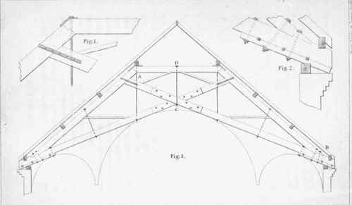
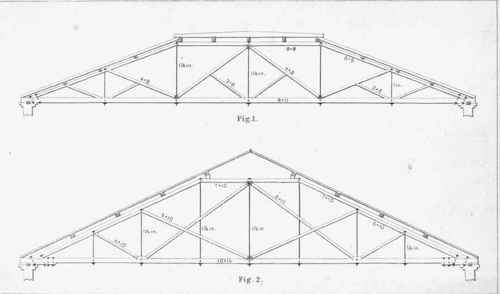
Plate IX
Fig. 1, on Plate IX., is a design for a low roof of wide span. The figures show the dimensions of timber for one of from sixty-five to seventy-five feet. It may be extended to ninety feet by a proportional increase in the size of the rods and timbers.
Fig. 2 shows a roof of from eighty to a hundred and twenty feet span. The figures on the engraving are calculated for one of a hundred feet, and should be increased or diminished according to its width.
The tie-beam in this design should be made of two four-by-fourteen-inch planks, with short pieces of two-inch planks at intervals between them.
Some of the bearings in each of these examples are designed to be of cast iron, as will be discovered by consulting the drawing.
Plate X
Plate X. exhibits two designs for curved roofs. The tie-beams of each are in two pieces, with a two-inch plank between them; and the struts, where they cross, are notched into each other, so that their sides may be flush with those of the beams.
Fig. 1 represents a segmental roof. The figures denote the size of timber for a span of seventy-five feet. If the span be increased to ninety feet, the size of the timber should be increased about one-seventh. The trusses may be placed ten feet apart; and the rafters, two by eight inches, notched two inches below the top of the curved rib. The purlins at aaa should be six by six inches: they are designed to give firmness to the roof at the joints. The bearings at bb, etc, are of cast iron.
Fig. 2 shows a design for a roof of from seventy to a hundred and twenty-five feet span. It is so designed, that a room may be finished above the tie-beams. If the span be great, with a room as proposed, the centre of the beam between the rods must be trussed, as shown in the examples on Plate V.; and the floor-joists should bridge upon, rather than cut into, the tie-beams.
Continue to:
My Books

