Bridges
Description
This section is from the book "Text-Book Of Modern Carpentry", by Thomas William Silloway. Also available from Amazon: Text-book of Modern Carpentry.
Bridges
The designing of wooden bridges was for many years intrusted to the architect, but has, of late, been considered as more properly belonging to the engineer. As the mechanical part of bridge-building must be done by the carpenter, a few examples are given in illustration of his province. Most of them have been designed for this work; and those remarks which have been made in reference to other descriptions of framing will apply equally well to this.
Plate XV
Fig. 1 of this plate represents what is familiarly known as "Howe's Bridge," taking its name from its inventor. The stringers A and B are of planks three inches thick, bolted together. These planks are of different lengths; and the joints should be well broken. The struts cross each other, without being notched or cut into; and, at their ends, they abut against a piece of white oak, as at C, Fig. 2. The rods are two in number to each section, as at DD, Fig. 3. The height of the sides, or trusses, should be about one-twelfth of the entire length of the span. The stringers should be wide enough to come out flush with the sides of the struts, and the oak-pieces must be as long as the stringers are wide. The depth of the stringer should be two-thirds of its width; and the struts one-twelfth the height of the truss, measuring between the stringers as ef. The diameters of the rods should be one-fourth that of the struts. An oak-piece, two inches thick and three inches and a half wide, is put at the nut at each end of the rod, as at g, Fig. 3.
Fig. 2 is the detail of the work at F; and Fig. 3, a sectional detail of that on the line HI. The figures on the engraving denote the dimensions of timber for a bridge a hundred feet long, eight feet high, and ten feet wide in the clear. Should a wider bridge be required, the number of sections must be increased. It is often the practice to place the floor-joists on the top of the upper stringer, instead of below; in which case, rails, or a balustrade, will be required.
Fig. 4 exhibits a design for a short bridge of from twenty-five to forty-five feet span. It is made by placing one timber above another, as shown in the drawing. The timbers being inclined, with oak-keys between them, and bolted together, a very strong truss is formed. The trusses should be about four feet apart, and the floor-joists three inches thick and twelve inches wide, placed twenty inches apart. These dimensions are for a bridge of thirty feet span.
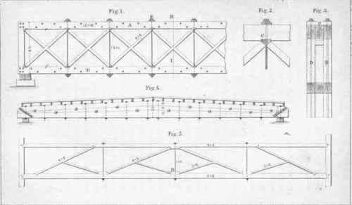
Fig. 5 exhibits a design for a common gallery truss. The bearing-pieces should be of oak.
The dimensions are for a truss of sixty feet span. It may be made somewhat flatter, if desired, and still be sufficiently strong for practical purposes.
Plate XVI
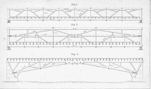
The figures on this plate exhibit designs for bridges of from fifty to ninety feet span. Should it be desired, the floor-timbers of Fig. 2 may be placed upon the centre rail, and the work above them will answer for the rails of the bridge: if this be done, the centre rails will need additional support by bracing. The dimensions are for bridges of sixty feet span; all the bearing-pieces being of the best dry and sound white oak, bolted with five-eighth-inch iron bolts. It may be well to remark here, that the floors of all bridges require strong horizontal braces from the side-stringers, crossing each other at the centre in order to prevent vibration.
Bridges
Smith Knight & Tappan Eng rs..
Plate XVII
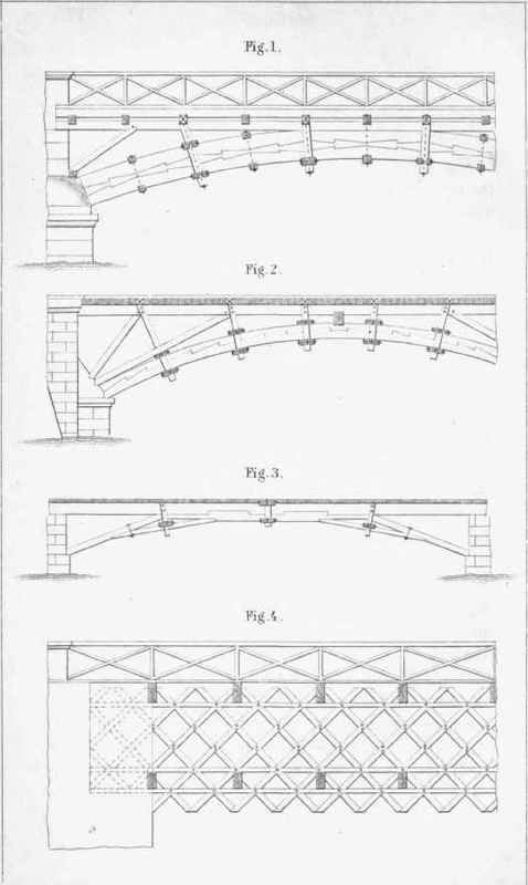
Fig. 1 represents a side-view of a timber-bridge over the river Meuse, in France. Its span is sixty feet, and its width twenty-eight feet. Each arch has four trusses.
Fig. 2 exhibits the design of a bridge over the river Rhone, in France. It is similar in principle to the example at Fig. 1, the trusses being secured by transverse timbers bolted together.
Fig. 3 represents a bridge over the river Loiret, near Orleans in France. Its span is sixty feet, and its width six feet six inches.
Fig. 4 shows part of a lattice-bridge invented by Mr. Ithiel Towne, of New Haven, Conn. Its span may be from seventy-five to a hundred and fifty feet. The lattice-framing is of planks three inches thick, and twelve inches wide, so arranged as to cross each other at right angles. They are confined together at the intersecting parts by oak tree-nails, an inch and a half in diameter, passing through each of the planks. The depth of the latticework should be about an eighth of the entire span. Plank-ribs are used at top and bottom on each side of the lattice-work; the sides being connected, top and bottom, at distances of twelve feet, by cross-timbers, and braced horizontally with diagonal braces. A bridge of this kind exists at Philadelphia, eleven hundred feet long, resting on ten stone piers. There is also another on the New-York and Harlem Railroad, seven hundred and thirty-six feet long, resting on but four piers.
Continue to:
My Books

