Iron Work. Continued
Description
This section is from the book "Text-Book Of Modern Carpentry", by Thomas William Silloway. Also available from Amazon: Text-book of Modern Carpentry.
Iron Work. Continued
It will be seen, by an examination of the plate, that at the line AB there is a tie-beam, which, with the work above it, comprises a segmental roof, complete in itself; and its rise may be increased as circumstances require. The dimensions designated by the figures are for a roof of eighty feet span, and should be increased one-eighth for a span of a hundred feet, and one-fifth for one of a hundred and twenty-five feet, - the rods being increased in the same proportion.
Pi. XI Roofs
Smith Knight &Tappan Eng rs..
Plate XI
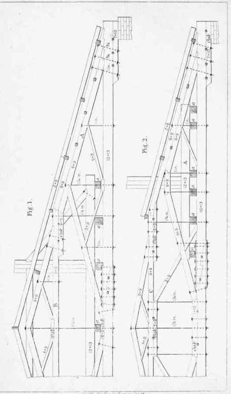
The figures on this plate exhibit the design of a portion of the large trusses which support the dome of the State Capitol at Montpelier, Vt.* The span is sixty-seven feet four inches between the walls, and the trusses receive no support from below. The bearing-pieces are of white oak, the rest of the timber being spruce. Each truss is composed of two parts, or sections, like those represented by the designs. The beams are placed fourteen inches apart, with short transverse ones extending from one to the other, as at aa, etc, with another crossing them, as seeb at A. Upon the beams last named stand the posts of the dome, which, when finished, will be forty-two feet in diameter. Its frame being octagonal, the two front and two rear posts are nearer together than the others, and consequently require a differently constructed truss. The student will readily discover, on examination, the manner in which the particular strains are resisted by the several parts of the work.
* These trusses, together with the framing of the roof and dome, employing eighty thousand feet of timber, were executed by Mr. Robert Gunnison, the master-carpenter, under the direction of Thomas E. Powers, Esq., the superintendent of construction, from drawings furnished by the author in 1857.
Plate XII
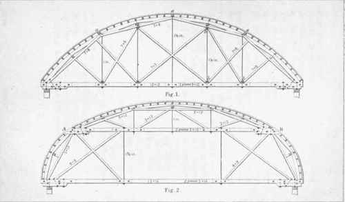
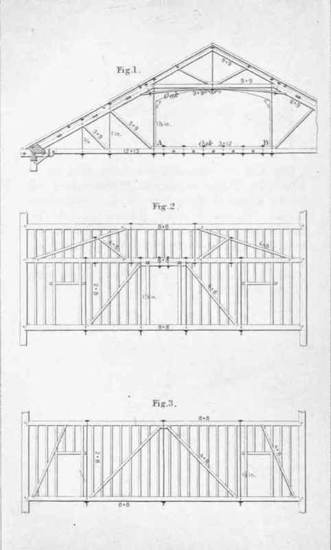
Fig. 1 of this plate shows the design of a roof over the Fitchburg Depot in this city. It was executed from drawings furnished by Mr. Charles G. Hall in the year 1848. The second floor of the building (some eighty feet wide, and a hundred and fifty feet long) is supported entirely by rods from the tie-beams. It has been loaded with people, at an average of a hundred and twenty-five pounds to the square foot, without any settlement whatever. The trusses are ten feet apart from centres.
Fig. 2 shows the roof of the Boston and Maine Railroad Depot, in Haymarket Square, Boston. It was executed from drawings made by Mr. Richard Bond, architect of the building. The trusses are twelve feet apart from centres. This roof remains as firm in every part as when first built; and, considering the quantity of timber used, it is a good roof.
The figures on each of these designs exhibit the dimensions of each part as taken from actual measurement.
Roofs
Pl.XII
Smith Knight & Tappan Eng rs..
Pl.XIII
Roofs
Smith.Knight & Tappaa.Engrs..
Plate XIII
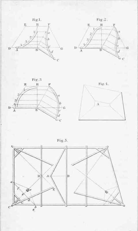
Figs. 1, 2, and 3 of this plate exhibit a method of drawing the angle-ribs of a roof, the outline of which is AH; and a portion of the plan, DEFG. Divide BH into any number of parts, as 1, 2, 3, 4, and draw lines through these points to the angle-line FB. From the points of intersection, on and at right angles with the line last named, draw abed equal to 1, 2,3, 4, measuring from BH to AH. Trace a line through the points, and the angle-rib is formed.
Fig. 5 illustrates the method of ascertaining the length and back of the angle-rafters of a hip-roof.
Let AB represent the pitch of the roof. From C, the corner of the plan, draw CD; and from D draw DE perpendicular to CD, equal to AB: from this point draw EC, which is the rafter required. To determine the back, of the rafter, we proceed as follows: Draw ab perpendicular to CD. On the centre c, with a radius cb (the edge of the rafter) describe the semicircle fed; then from e draw ea and eb, which will be the angle of the rafter at e.
Where the plan of a roof is bounded by lines which are not parallel, it is the usual practice, in order that the sides of the roof may be of the same inclination, to truncate the work, as shown at A, Fig. 4.
Plate XIV
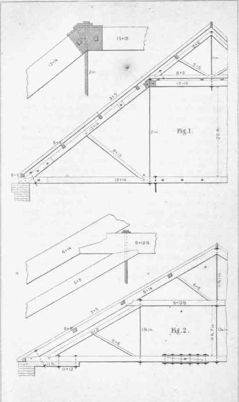
Fig. 1 of this plate exhibits a design for a roof of large span. The figures designate the dimensions of timber for a span of eighty feet. With a proportionate increase of the size of rods and timber, it may with safety be extended over a span of a hundred and twenty-five feet. The beam should be made in two sections, the centre portion between the rods trussed, and an oak-plank three inches thick bolted to the top of the beam, as seen at AB.
Roofs
Pl.XIV
Smith Knight & Tappan Eng rs..
Continue to:
My Books

