Chapter XXXIII. Distillation Under Reduced Pressure
Description
This section is from the book "Distillation Principles And Processes", by Sydney Young. Also available from Amazon: Distillation Principles And Processes.
Chapter XXXIII. Distillation Under Reduced Pressure
Vacuum distillation in the petroleum industry has not up to the present received the attention it deserves. Plants for the distillation of lubricating oils are often operated under vacuum, but this is seldom sufficiently high to give the best results, in many cases, indeed, being so low as to have little marked effect on the distillation. The advantages of distilling under vacuum are: -The fractions are distilled off at relatively lower temperatures, cracking or decomposition being thus largely avoided. The distillates obtained are of better colour and of higher flash-point; the residues are also of better quality, as they have not been cracked and so contain little or no free carbon. From wax base oils, for example, a better yield, not .only of the heavier lubricating oils but also of the higher grade waxes, may be obtained. Good distillates suitable for concentrating to cylinder oils may thus be obtained. The difference in character between wax and asphalt oils, as far as yield of lubricating oils is concerned, largely disappears under high vacuum distillation.1 Vacuum distillation plants are naturally more costly as regards capital outlay and operating wages. This is, however, counterbalanced by the fact that the products obtained are of better quality and require less subsequent chemical treatment. The system finds application, in the petroleum industry, chiefly for the manufacture of lubricating oils ; but there is no reason why it should not be applied to other operations as well, the treatment of which lies outside the scope of this work.
Vacuum distillation may be applied either to periodic or continuous distillation. The simpler forms of plant consist of a still of the ordinary type, structurally strengthened to withstand the external pressure, with dephlegmators, coolers, and receiving boxes, all under vacuum. The system is connected to the top of a barometric condenser and exhausted to the required vacuum by an air pump. Many forms of plant, differing in detail but similar in principle, have been devised, e.g. that of Henderson, designed as far back as 1883 (Eng. Pat. 5401 of 1883 and 17332 of 1889), those of Lennard (Eng. Pat. 944 of 1892) (applied in the coal-tar industry), of Zaloziecki, Palmer, Wanklyn and Cooper (Eng. Pat. 4097 of 1893) and others, all of which operate at relatively low vacuums. Fig. 150 illustrates the main features of a simple vacuum plant.
1 L. Singer, Petroleum, Berlin, 10, 605. 352
The still is of the ordinary type, internally strengthened to withstand the external pressure. It is fitted with perforated pipes in the usual way, as the distillation is invariably conducted with the aid of steam.
The vapour pipe, which is always of large diameter, is connected to several domes on the still. It leads to dephlegmators, or atmospheric condensers, where the heavier fractions are condensed. The first air-cooled condenser often takes the form of a number of large diameter horizontal pipes. The condensate from these air coolers flows through a cooler into a receiving tank connected to the air pump. The receiving tanks are in duplicate, so that that which receives the distillate can always be kept under vacuum, while the other is being pumped out. Several air-cooled condensers may be employed, and also water-cooled condensers, the condensates from which run off through coolers to receiving tanks under vacuum. The vapours containing the lightest fractions and the steam are finally condensed in a spray condenser, elevated and connected with a water pipe terminating in a water seal below, of such a height that it functions as a barometer tube, the vacuum in this barometric condenser being maintained by an air pump. An apparatus designed for working at high vacuum is that of Steinschneider (U.S. Pat. 981953 of 1911). One of the chief objections to the previously described schemes is that the receivers for the distillates are under vacuum, an inconvenient arrangement, as they are not under complete observation and control. Further, if evacuation takes place via the distillate receiver, the lighter vapours are retained in contact with the distillates, whereas they should be removed as quickly as possible. This could be avoided by placing each receiver tank at the bottom of an oil barometer, but this would necessitate either building the plant very high, or else much excavating, both of which are expensive. Steinschneider avoids these difficulties in the following way (Fig. 151). The distillate vapours pass from the still s through dephlegmators or air condensers d to the cooler c and on to the elevated barometric condenser b. The distillates condensed in the dephlegmators d flow away through the coolers e to the receivers r, which may be fitted with floats for regulating the level of the liquid contained in them.
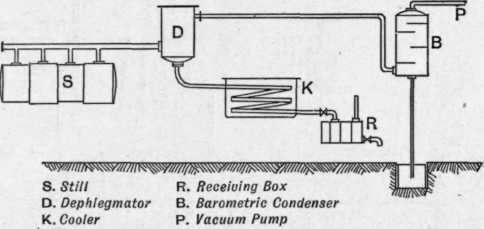
Fig. 150. - Simple vacuum distillation plant.
The fractions collected in these receivers are pumped out by low level pumps, each fraction having its own pump, into the distributing box t. The non-condensable gases are sucked out of the elevated condenser b (which stands at the top of a barometric column) by the air pump f.
This arrangement enables the distillation to be carried out under high vacuum without its being necessary to make the heights of the discharge pipes g correspond to the vacuum. By employing these pumps p, it is possible to make the fall of the discharge pipes G such that the column of liquid in this pipe requires to have merely that height which this pump is able to maintain when evacuating.
There would appear to be no advantage in applying vacuum distillation to the distilling off of the volatile fractions from crude petroleum, as the temperatures at which the distillates come off are low and as extra condensers or scrubbers at atmospheric pressure would be required to retain the lighter vapours.
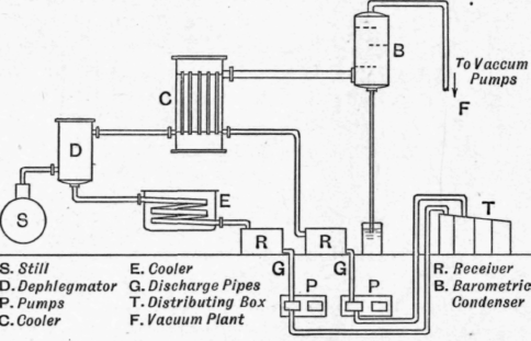
Fig. 151. - Steinschneider's vacuum distillation plant.
In this connection a few words concerning distillation and condensation at higher pressures may not be out of place. Distillation at high temperatures and under higher pressure is the principle involved in many patented processes for the cracking of petroleum. By such methods a partial decomposition of the heavier into the more valuable and lighter fractions is obtained. Such decomposition is, under these conditions, accompanied by increased losses owing to the formation of hydrogen and uncondensable gases, and the quality of the residue is also impaired owing to the formation of coke. Excessive coke formation is, indeed, one of the chief drawbacks of such systems. Systems of condensation under pressure are much in use for extracting further very volatile fractions from petroleum distillates, especially from the natural gas so often given off at the well heads, as natural gas may be regarded as the distillate from crude petroleum which comes off at the ordinary temperature. The volatile fractions so condensed are largely used for blending purposes in the United States and elsewhere, being usually termed "casinghead gasoline." In place of compression plants, absorption plants, using a gas oil or other relatively high boiling distillate as absorbing agent, are frequently employed. De Brey and the Bataafsche Petroleum Mij. (vide Eng. Pat. 123522 of 1919) have patented a plant for the distillation and rectification of such volatile liquids under pressure. The discussion of cracking processes, however, lies outside the scope of this volume.
Continue to:
My Books

