


A Home-Built Alternating-Current Motor. Part 3
Description
This section is from the book "Handy Man's Workshop And Laboratory", by A. Russell Bond. Also available from Amazon: Handy Man's Workshop And Laboratory.
A Home-Built Alternating-Current Motor. Part 3
Drill the 37 holes for the slots with a No. 3 drill, which is 0.213 of an inch in diameter, and make sure that they are deep enough to pass clear through the second copper plate. After the holes are finished it will be necessary to clamp the laminae to the faceplate so that the four bolts in the middle may be removed to permit of the inside being bored out. One way to do the clamping is to pass six or eight 3/16-inch bolts through as many of the 37 slot holes, but the method shown in Fig. 210, is better. Four 3/8-inch bolts applied as shown will grip the lamina; quite firmly. Bore out the inside smoothly to a diameter of 2 1/2 inches, and before removing the laminae from the face-plate fit three or four wood sticks in the small holes to keep the bundle of laminae from falling apart. The final operation is to put the plates in a vise and with a thin hacksaw cut through the little bridge of metal that separates each of the 37 holes from the outside, when the plates will appear as in Fig. 215. The saw-cuts ought not to be more than 1/32 inch wide. If the saw cuts wider than this, it is well to grind off some of the "set" by holding the blade flat against a grindstone.
Clean and shellac the rotor core plates as was done with those of the stator. and guard against mixing them. Before separating the plates file a well-defined groove inside the central hole, so as to make a slight notch in each plate to serve as a mark, and then pass a stout string through the hole and tie the ends together.
In Fig. 220 are shown details of the rotor shaft, spider, and "winding." The material required for the shaft is a piece of cold-rolled steel 9/16 inch in diameter and 7 inches long. This should be held in the lathe chuck while truing up each of the ends and drilling the centers in them, after which it may be supported between the lathe centers and finished all over. Make the central portion 1/2 inch in diameter and 2 1/4 inches long, and the bearing portions 7/16 inch in diameter. The latter, after being turned and filed as smoothly as possible, should be given a polish with a piece of very fine emery paper wet with machine oil.
The best material for the spider is a brass casting, for which it is not difficult to make a wood pattern by turning off a piece of white pine in the lathe. A very good substitute for the brass however, can be made of Babbitt metal, or of ordinary plumbers' solder, which can be cast at home in a sand or plaster of Paris mold, or even in a wooden one. The rough spider casting should be drilled with a 31/64-inch drill, reamed to 1/2 inch to fit the shaft, and secured to the latter by pinning with a small steel pin. If one of the suggested methods of making the casting at home be adopted, there is no reason why the spider may not be cast right on the shaft itself, thereby saving the trouble of fitting it to the latter afterward. The cylindrical surface of the spider must be turned in the lathe to a length of 2 1/4 inches and a diameter of 2 1/2 inches, or rather, to such a diameter as will permit of the rotor plates being put on easily without being loose enough to shake. On the inside the spider should be finished all over, to make it as light as possible and to keep it balanced. The rim needs to be about 3/32 inch thick, and the arms and the hub about 3/16 inch thick. The six holes shown at A in Fig. 220 are not merely for ornament, but are to allow of air passing through the machine for ventilation.
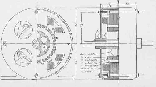
Fig. 220 - Details of complete motor.
Assemble the rotor core plates on the spider with one of the copper or brass plates at each end. Use only enough of the steel plates to make a length of 1 7/8 inches, which will make the length when the end plates are in place just 2 1/8 inches long, and leave about 1/16 inch of the spider projecting at each end. For the "inductors" to go in the slots, procure 7 1/2 feet of No. 4 copper wire, which is 0.20431 inch in diameter, and after straightening it out saw off thirty-seven pieces each 2 1/4 inches long. Clean these carefuliy by scraping each of the ends for about 1/4 inch with a knife. The middle portions may be left as they are, but if the best results are desired, it is worth while to glue on a wrapping of thin paper to insulate the inductors from too much contact inside the slots. Insert the wires in the slots and rivet all the projecting ends by tapping lightly with a hammer until each one is expanded enough to prevent its dropping out. The inductors are next to be soldered to the end plates, to make good electrical contact all around. To do this, stand the rotor up on end, and apply some good quality soldering salts or paste to the riveted heads, end plates, and spider. Use a hot soldering copper, and apply the solder very generously so as to bury all the rivet heads out of sight. When both ends have been thus treated, place in the lathe again and true up the soldered rings by turning off the solder until the copper inductors begin to show. This will complete the rotor except for balancing. Take two smooth metal rods of any convenient size, and support them about 4 inches apart on the upper edges of an empty box, as if to form a miniature pair of parallel bars. Have them as nearly level as possible, and place the rotor shaft with one end on each bar. If the rotor is out of balance it will, of course, roll over and stop with the lighter side up. Make a mark at this place, and apply a little solder to the inside of the spider as near to the arms as possible. Increase or reduce the weight as required until the rotor will lie indifferently in any position in which it may be placed on the rods. This type of rotor is known as the "squirrel cage."
In Fig. 220 there are also shown some details of a suitable external casing for the motor. This is intended to hold the bearings and the stator plates in a fixed relation to each other, and at the same time to protect the delicate stator coils from accidental injury. It is to be cast in two halves exactly alike, so that both "shields" may be made from the same pattern. Brass castings are the easiest to finish in the lathe, but iron is much cheaper. In the selection of material, and in the arrangement of the details of the casing and bearings, the amateur is advised to use his own judgment and skill, provided that the following points are observed. The rotor must be supported in the exact center of the stator field, so that the air-gap under each of the four poles will be uniform, or 1/32 inch all around. This desired result will be secured as a matter of course, if the seat for the bearing B, Fig. 220, the four internal lugs L, and the face F be all finished in the lathe at one chucking of the casting. The four bolts passing through the stator plates must be long enough to pass also through the end shields, to clamp the whole together as shown. The bearings may be of either brass or Babbitt metal, and the rotor shaft should turn freely in them without being loose enough to shake. Allow sufficient room between the two bearings so that the shaft has an "end play" of nearly 1/8 inch, and provide oil cups of some kind to furnish plenty of lubrication. In the end shields there must be several holes to permit air to circulate through the motor and help to keep it cool. If the lathe on which the shields are to be finished is not too small, it is a good plan to have suitable feet cast on them, so that the finished motor may be conveniently bolted fast in the place where it is to be used.
Continue to:


My Books

