


A Home-Built Alternating-Current Motor. Part 4
Description
This section is from the book "Handy Man's Workshop And Laboratory", by A. Russell Bond. Also available from Amazon: Handy Man's Workshop And Laboratory.
A Home-Built Alternating-Current Motor. Part 4
All parts of the motor have now been described, except the winding for the stator, which consists of four copper "dampers" and four coils of wire. The copper dampers are shown in detail in Fig. 221. Each one can be cut from a solid piece of copper sheet 1/8 inch thick, or they may be built up of several thinner pieces having the same total thickness. If the latter method be adopted, the small pieces should he soldered together after they are finished, so that they can be handled as single units.
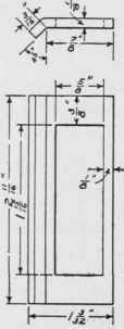
Fig. 221 - Cotton damper.
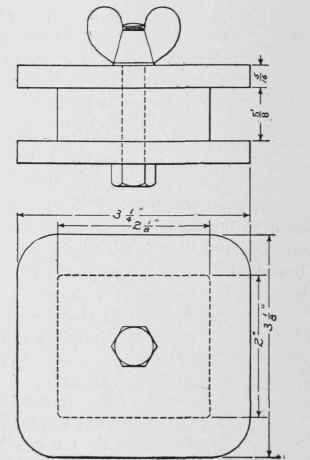
Fig. 222 - Coil winding form.
Figs. 222 and 223 show the winding form for making the stator coils. This consists of three blocks of wood held together by a bolt and revolved in the lathe by gripping the holt head in the chuck. The central block, measuring 5/8 by 2 by 2 1/8 inches, is best made of a piece of hard wood, such as maple or mahogany, and it must be quite accurate in each of its three dimensions, since these fix all of the dimensions of the coils. The four corners of the block must be very slightly rounded, to avoid the difficulty of having to bend the first turns of wire around square corners. About two pounds of No. 21 single cotton-covered magnet wire is required for the four coils. Each coil is to have 165 turns, put on in close, even layers. The number of turns is so important that it is not well to trust to the mind to keep tally while winding. Set the gears to feed at some convenient rate, say ten threads per inch, and run the tool carriage to the extreme right-hand end of the bed and make a chalk mark on the bed at that position. Then, when the winding is started, throw in the screw feed, and the movement of the carriage to the left of the chalk mark will count the turns automatically, for when the carriage has traveled 16 1/2 inches, as measured by a foot rule, the spindle will have made the required number of turns. Before beginning the winding, it is necessary to provide means for holding the turns of the coil together so that the blocks may be afterward removed without any danger of the coil coming apart. For this purpose, nothing is better than four strips of cotton cloth about half an inch wide placed crosswise in the space where the wire is to be wound. These may be readily held in place by the first turn of wire, or, better still, by a strip of canvas or tough paper cut 3/4 inch wide, wrapped once around the form, and glued to itself like a cigar band. Do not attempt to wind the coils by power, but turn the lathe head over a little at a time by hand, so that the wire can be laid on in closely-fitting, smooth layers. Start the winding near the middle of one of the longer (2 1/8-inch) sides, and have it end near the same place. It is well to paint the inner end, or terminal, black for the purpose of easy identification later on. After putting the required number of turns on a coil, tie the ends of each of the four pieces of cloth together and remove the blocks.
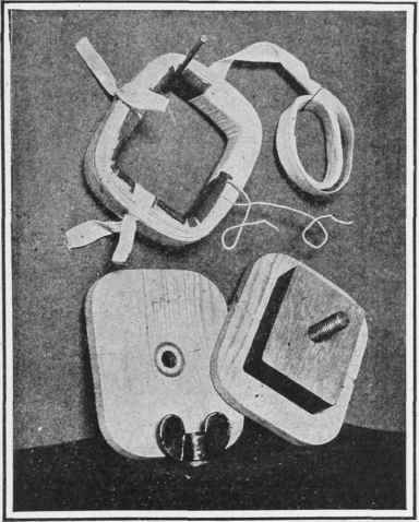
Fig. 223 - Coil winding form and partly taped coil.
Fig. 223 shows the method of applying a final covering of tape for protection and insulation. Very thin cotton tape about 1/2 inch wide is suitable, and it should be lapped on itself about half way in the winding, so that the coil is really protected by two layers. As the taping progresses, the temporary ties may be removed, but the inner band of canvas or tough paper is to be left there as shown. Where the inner lead or terminal comes out across the other layers of wire a piece of paper about 1/2 inch square should be slipped in to guard against possible short-circuits.
The final assembly is next in order. (See Fig. 224.) The stator plates, in addition to being held together by their four bolts, should be tied with string, as shown. The coils are to be placed on the poles all in the same position, i. e., all of the faces which were next to the lathe head during the winding must be turned either toward the rotor or away from it. Do not force the coils over sharp corners on the poles and run the risk of cutting through the insulation. If the coils do not go on easily; file the corners of the poles round and smooth. The coils and the dampers, when once in place as shown, are most conveniently held in position by bending outward the first lamina on each side of the pole tips, which holds them on as if they were riveted there.

Fig. 224 - Assembling the parts.
The four coils must be connected in series so as to make the poles alternately positive and negative. One way to do this is as follows: Beginning at any given point, connect the inner end of coil No. 1 to the inner end of coil No. 2. Next connect the outer end of coil No. 2 to the outer end of coil No. 3, and finally connect the inner end of No. 3 to the inner end of No. 4. This will leave free the outer ends of coils No. 1 and No. 4. If the coils are not wound all in the same direction, or are not assembled at all in the same position relative to their respective poles, or the inner and outer leads become confused, then the polarity of the poles will not come out right. To make sure on this point connect the two free ends of the winding to a battery of one or more cells, and present a pocket compass to each of the pole faces in succession. They must show alternately north and south all the way around. In case they do not, some mistake has been made, and this can be easily corrected by exchanging the connections of any coil that shows up wrong. When everything is right, it is worth while to solder the connections and cover them with tape for insulation. Do not apply alternating current to the coils unless the rotor is in its place, properly mounted in its bearings, and left free to turn. If this caution is not observed, the coils will be soon burned up, as their resistance alone is not sufficient to prevent their taking too much current from the line.
When assembling the stator in the casing, see that no part of the winding or its connections is pinched or grounded. If any connections lie against the frame, slide pieces of tape under them and glue them fast. Perfect insulation is much more necessary in alternating-current magnets than in direct-current. A short circuit between a few of the turns of a coil does no particular harm on direct current, but in the case of alternating current tremendous currents are set up in the short-circuited turns and the entire coil is soon burned up.
The two leads or terminals to the winding may be attached to two pieces of rubber-covered flexible cable brought out through holes in the casing for the purpose of connecting to the alternating-current mains. A much neater way, however, is to attach two small binding posts to the casing, from which they can be insulated with fiber thimbles and washers. No pulley has been shown in the drawings, as the form and dimensions of this will depend on the particular kind of work the motor is expected to do. For ordinary service a pulley of about 2 inches in diameter by 1 1/8 inches face will probably give the most satisfaction.
No starting box is required for this type of motor. An ordinary socket plug and lamp cord is all that is needed. The rotor, on account of the unbalanced pull exerted by the four dampers on the poles, will start to revolve as soon as the current is turned on, unless it is stuck in its bearings or stalled by an overload.
Continue to:


My Books

