


415. Joints Of Framing
Description
This section is from the book "Elementary Principles Carpentry", by Thomas Tredgold. Also available from Amazon: Elementary Principles Of Carpentry.
415. Joints Of Framing
The object to be obtained by a system of framing is to reduce all the pressures into the directions of the lengths of the pieces composing the frame; therefore the form of the joint should be made so as to direct the pressures into the axes of the pieces. As when the direction of the strain does not coincide with the axis of the piece, the strain will be much increased. Now, from the form of the joints commonly employed, it must generally happen, that by shrinkage, or settlement, the joints will bear only upon the angular points of the shoulders; which not only gives a considerable leverage to the straining force, but also, in consequence of the whole bearing being upon an angle, the piece must be either indented or crippled by the strain, which would of course cause a further settlement. The extent of the evil arising from partial bearings becomes very manifest when the strains are considerable. In the centres of the Bridge of Neuilly seven or eight pieces in each frame were split from end to end, and many others were bent considerably. The joints were not what would be called very oblique, otherwise the effects might have been more serious. Perronet was aware of the cause, and in order to correct it, he formed the abutments according to an arc of a circle, of which the other extremity of the piece was the centre.
This method was adopted for the joints of the centre for the Bridge of Sainte Maxence, and also in that for the Bridge de la Concorde, at Paris; and it was effectual in preventing the splitting and bending of the pieces.*
* ' British Carpenter,' Introduction.
Circular abutments have been strongly recommended by-Professor Robison,† and they certainly might be employed in many cases with advantage. The principle is similar to the well-known contrivance called the ball and socket; and to the joints of animals, where, with considerable latitude of motion, uniformity of pressure is preserved. They require more labour, but that would be a comparatively trifling object in a framing of importance.
It is obvious, that when motion takes place in the opposite end of the piece, a corresponding movement will take place at the joint, and when the radius of curvature at the joint is small, the motion there will scarcely be perceptible. For in a roof of 30 feet span a sinking of six inches in the middle would not cause the joints to slide more than one-tenth of an inch.
We will now proceed to describe some of the joints of most common occurrence, and endeavour to point out improvements that might be made in some of them.
When one piece is perpendicular to another, as, for example, a post upon a sill, the usual, as well as the most easy method, is to make the joint square, with a "stub" or short tenon of about one-fourth of the thickness of the framing, to retain it in its place.
But if the joint be not very accurately cut, the whole load will bear upon the projecting parts; consequently, the centre of pressure will seldom coincide with the axis of the post, and its power of resistance will be much lessened.
If, instead of cutting the joint square, it were cut to form
* Gauthey, ' Construction des Ponts.'
† In the 'Encyclopaedia Britannica,' art. Carpentry, and 'Parliamentary Report on the Improvement of the Port of London.' an angle, as shown by Fig. 142, then a very little care in cutting the joint would make the centre of pressure coincide with the axis.
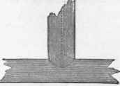
416. Now whether the joint be square or angular, a slight inclination from the perpendicular will throw the pressure upon one corner; but if the joint be described from a centre situate in the axis, and with a radius not much greater than half the breadth of the post, as shown in Fig. 143, then, with any change of position, the joint will slide till the pressure is uniform; and if the joint be moderately well made, the pressure will not act with any sensible leverage upon the post. But if the post be of any considerable length, a rounded end is not so strong to resist compression as a square one, particularly if the latter be fixed (see Sect. II., Art. 152).
Fig. 142.
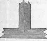
Fig. 143.
417. When the pieces to be joined are not at right angles to one another, the joints may be similar to those used for the principal rafter of a roof. But before we proceed to describe these joints, it is necessary to state that the direction of the strains, as well as their magnitude, remain sensibly the same, whatever may be the form of the abutting joints, except so far as the form of the joint alters the points of bearing; which may in some cases cause the pressure to act with a leverage nearly equal to half the depth of the beam. The strength of the joint itself depends upon its form, as it may be so made that there will be a tendency to slide, which it would be well to avoid, without having recourse to straps.
The resistance at the joint is always most effectual when the abutment is perpendicular to the strain, but where the angle formed by the inner sides of the pieces is very acute, this kind of abutment cannot be obtained, at least not without wounding the tie too much.
Let ABC, Fig. 144, be the joint of a principal rafter upon the tie-beam; where the dotted line A B shows the direction of the straining force, and B a is one of the abutting surfaces. Draw a c perpendicular to B a; then, by the principles of the resolution of forces (Sect. I., Art. 28) c a will represent the force pressing on the inclined part, B a, of the joint; and there will remain a force represented by B a to be sustained by the abutment Bd. And as this abutment will resist the force most effectually when it is perpendicular to it, therefore B d should always be perpendicular to B a; the same will be true in whatever direction the straining force acts.
Fig. 144.
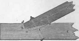
Fig. 144 shows one of the best and most common forms of joint; Ba and Bd are the abutting surfaces, which are to be perpendicular to each other; and b e shows the tenon, the thickness of which may be about one-fifth of that of the framing. This joint might always take a better hold of the tie-beam than it is generally made to do, without any risk of weakening it. In general, B d should somewhat exceed half the depth of the rafter, and the joint should be left a little open at a, in order that it may not be thrown off at B, by the settling of the roof.
Continue to:


My Books

