


Of The Composition And Resolution Of Forces
Description
This section is from the book "Elementary Principles Carpentry", by Thomas Tredgold. Also available from Amazon: Elementary Principles Of Carpentry.
Of The Composition And Resolution Of Forces
7. The resolution of forces consists in finding two or more forces which shall have the same effect as a single force. For the weight W (Fig. 1) might be sustained by a vertical force in the direction c C equal to it; or this vertical force, it is obvious, may be resolved into two forces in the directions of the beams capable of producing the same effect as the vertical force C c.
8. The composition of forces consists in finding one force that shall produce the same effect as two or more forces acting in different directions. This is nothing more than the reverse of the resolution of forces, and may be accomplished in a similar manner.
9. If a vertical line C c (Fig. 1) be drawn through the centre of the weight, and a c be drawn parallel to the beam A C; also b c parallel to B C; then the relations between the weight and the pressures will be found by the following proportions:
As the line C c, Is to the line C b; So is the weight W,
To the pressure in the direction of the beam A C. Also, As the line C c,
Is to the line C a;
So is the weight W,
To the pressure in the direction of the beam C B.
To those who are acquainted with the principles of mechanics the truth of the principle from which these proportions are derived requires no illustration; but such as have not had the advantage of that branch of learning may, by having recourse to the following simple experiment, not only satisfy themselves of its truth, but also render themselves more familiar with the nature of forces.*
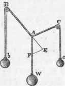
10. Let a thread or fine line be passed over the pulleys B and C (Fig. 2), and let a known weight be attached to each end of the line, as at b and c; also let another thread be knotted to the first one at any point A, and attach a known weight to the end W. Then if the sum of the weights b and c be greater than the single weight W, there is a certain position in which the assemblage will be at rest; and if it be deranged by pulling at any of the weights it will return of itself to the same position when left at liberty. Therefore, in that position, and in that position only, the weights will balance one another, or be in equilibrio. Now, if the positions of the threads, when the weights balance one another, were drawn upon paper; and, from a scale of equal parts, A F were made equal to the number of pounds in the weight W, and the line B A were continued to E, and the line F E drawn parallel to A C, then F E measured by the same scale of equal parts would show the number of pounds in the weight at c; also the measure of the line A E would be equal to the number of pounds in the weight b.
Fig. 2.
* The reader who wishes to have more scientific information on the subject will find it ably handled in Gregory's 'Mechanics,' vol. i., chap. 2; he may also consult Rankine's 'Applied Mechanics,' Fen-wick's ' Mechanics of Construction,' or Byrne's ' Elements of Practical Mechanics.'
If the three weights he equal, then the three lines A F, F E, and A E will be equal, and the angles formed by the threads round the knot will he equal.
11. And universally whenever the directions of three forcees are in the same plane, and meet in a point, and are in equilibria, those forces will be represented in magnitude by the three sides of a triangle drawn parallel to the directions of the forces.
12. Consequently, if a body be kept at rest by three forces, and any two of them be represented in magnitude and direction by two sides of a triangle, the third side taken in order will represent the magnitude and direction of the other force.
13. Also because the sides of triangles are as the sines of the opposite angles, it follows that when three forces keep a body in equilibrio, each force is proportional to the sine of the angle made by the direction of the other two. Thus, if the weight W (Fig. 2) be as the sine of the angle A E F, the weight b will be as the sine of the angle A F E, etc.
It may, however, be observed, that the designs of framing are always drawn on paper to a scale; hence the proportions of the forces may be obtained immediately from the figure without the trouble of calculation, and the values so obtained will bo accurate enough for any practical purpose. This method then will be adopted in the following pages whenever it is found most convenient.
14. Again, considering the combination of forces in Fig. 1; let the vertical line C a be drawn, and by a scale of equal parts make C c equal to the number of pounds, hundredweights, or tons contained in the weight W. Then draw c b parallel to B C, and c a parallel to A C; and C b, measured from the same scale, will show the number of pounds, hundredweights, or tons by which the beam C A is strained; and, in like manner, C a will be the measure of the strain on the beam C B, in pounds, hundredweights, or tons. The pressure is not altered by making the beams longer or shorter, so long as their positions remain the same; but the power of a beam to resist pressure is much lessened by increasing its length. The effect of this power will be considered in another part of the work (see Section II.). Only it may here be remarked, that when one beam is much longer than another in a system of framing, the position of the line of direction of the weight will vary a little from its intended position; because a beam of ten feet will compress twice as much as one that is only five feet long, and this will cause a corresponding change in the directions of the forces. Also if a beam that has to sustain a pressure in the direction of its length be joined in several places, it will yield more than one that has no joints except those at its ends; and the yielding will be nearly in proportion to the number of joints, supposing them all to be equally well made; for it is impossible to make a joint that will not yield in some degree.
Changes of form in an assemblage, or system of framing, almost always increase the effect of the weight, and often produce cross-strains that are attended with the worst consequences when such changes are not foreseen, and provided for accordingly.
Continue to:


My Books

