


Joints Of Framing. Continued
Description
This section is from the book "Elementary Principles Carpentry", by Thomas Tredgold. Also available from Amazon: Elementary Principles Of Carpentry.
Joints Of Framing. Continued
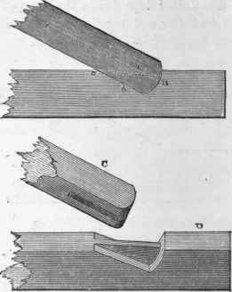
418. Fig. 145 is a form that is approved by some writers, but by others it is considered inferior to the one already described. The dotted line shows the form of the tenon; but it would be better put together in the same manner as the joint to be described in the next article.
FIG. 145.

Fig. 146.

419. Fig. 146 is a very good form for a joint, as o d is perpendicular to the strain, considering the strain to be in the direction of the rafter, which is near enough to the truth for. our present purpose. The best method of forming this joint is shown by the projected sketches A and B; as by this method it is easy to see when they are accurately fitted; whereas in a mortise-and-tenon joint this cannot be done, because it is easy to conceal any defect. Care should be taken, however, to prevent the pressure from coming on the upper part at d, which would be liable to split off.
420. Fig. 147 shows a joint with a curved abutment; the line B A represents the direction of the strain; and c the centre, which should be in this line. The radius for describing the joint should be greater than half the depth of the rafter; and the part between a and b of the joint should be left open to admit of any settlement that may take place. The projected sketches, C and D, show the manner of forming the joint.
Fig. 147.
Sometimes double abutments are used in joints, but they require great accuracy in workmanship, and also that the roof should not settle more nor less than the workman has allowed for, in order that both may have an equal bearing. For this reason one good abutment is preferable to two.
Fig. 148.

Professor Robison very justly remarks, that " because great logs are moved with difficulty, it is very troublesome to try the joints frequently to see how the parts fit; therefore we must expect less accuracy in the interior parts. This should make us prefer those joints whose efficacy depends chiefly on the visible joint."* But double abutments still further increase the difficulty, without adding anything to the security of the joint.
421. The joint at the upper end of a principal rafter differs from that at the lower end in some respects; but the differcnce is not material as regards the principle of forming the joint. Making the king post larger at the head enables us to get a more effectual abutment; and this abutment in common joints should be square to the back of the rafter, as at A, in Fig. 81, Art. 250, with a short tenon as shown by the dotted lines. When the head of the post is not sufficiently large to get the abutment square to the back of the rafter, it is usual to cut it as at B. In either case the joint should be left a little open at a; so that when the roof settles it may not bear upon the acute angle.
* ' Encyclopaedia Britannica,' art. Carpentry.
Fig. 149
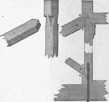
The same remarks will apply to all similar joints; such, for example, as the joints between the braces or struts and king post at C and D, Fig. 81, Art. 250.
But the joints D and B would be better formed in the manner shown at A and B, Fig. 149, where a b is at right angles to b c. The reason for this form is given in Art. 419. The joints may be made as shown by the projected sketches E and F.
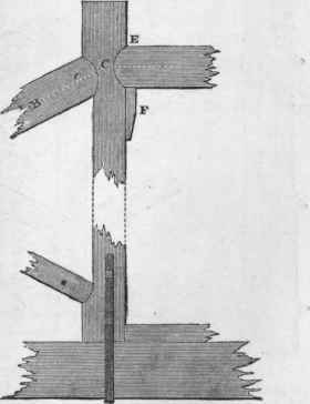
422. A joint with a curved abutment is shown by Fig. 150; B C represents the middle of the depth of the rafter, and c the centre from which the curve is described; the radius C c, should not be less than half the depth of the beam. A and D, Fig. 148, are projected sketches of the joint.
In Fig. 150, E shows a joint for the straining beam of a roof, and G, Fig. 148, is a projected sketch of the joint. As a further security, the piece F might be nailed upon the queen post C. The lower part of Figs. 148 and 150 show the joints for struts or braces.
Fig. 150.
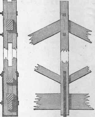
423. Instead of the common method of framing the king or queen posts between the ends of rafters and the like, it is much better to make the rafters abut against one another, end to end; and to notch a piece on each side, and to bolt through them as stated in Art. 254. Fig. 82, Art. 254, and Fig. 151 show this method of joining, which has been long used for centres, bridges, and roofs.*
Fig. 151.
The German carpenters put a piece of lead between the abutting surfaces of their joints, in order to equalize the pressure. This precaution is not, however, so necessary in timber-work as it is in stone-work; a plate of cast iron between the surfaces would be more useful.
* Rondelet,' L'Art de Batir.'
Continue to:


My Books

