


Plates and Illustrations. Part 4
Description
This section is from the book "Modern Carpentry And Building", by W. A. Sylvester. Also available from Amazon: Modern Carpentry And Building.
Plates and Illustrations. Part 4
The end sills should be 7 or 8 inches wide, so as to get a good nailing for the ends of the upper floor-boards, as shown in Fig. 31; while if the sills are narrow, as seen in Fig. 32, the ends of the upper floor-boards have no timber to nail into.
Plate 11. Fig. 33. An end elevation of a two and one-half story dwelling-house. - The dotted lines at g g show the position of the girts or ledger-boards on the side of the building, being put down so that the floorings may set on them, and come even with the top side of the end girt.
Plate 12. Fig. 34. The side elevation of the same house as Fig. 33, being represented with side girts. - Another way, and in some respects to be preferred to this way, is to use ledger-boards instead of girts, which allows the studding to run whole length from the sill to the plate. Braces may be put from the sills to the posts, and from the plates to the posts. With girts there are more chances to put braces.
Plate 11.
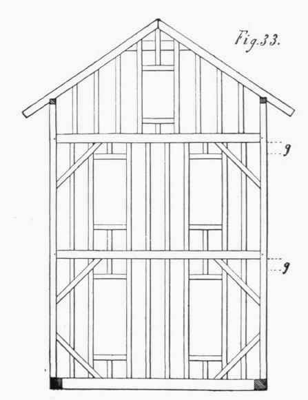
Plate 12.
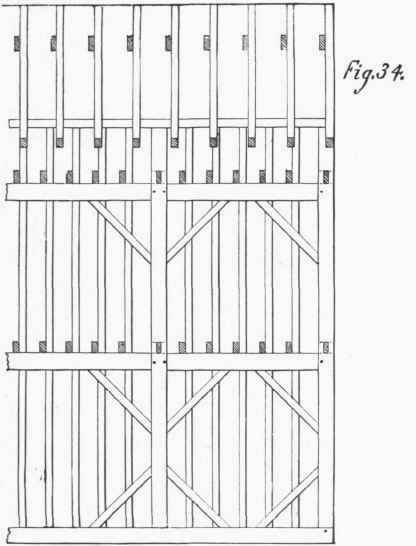
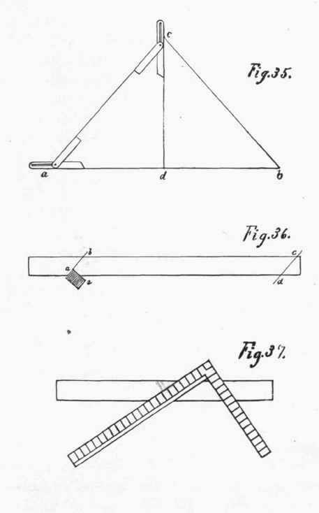
Plate 13. Fig. 35 shows the method of finding the bevels of rafters for pitch roofs. Let a b be the width of the building, which may be drawn to the scale of one and one-half inches to the foot. - each one-eighth inch of the drawing representing one inch, - and c d be the rise. Join a and c, which gives the pitch of the roof. At c is seen the bevel for the top of the rafter, and at a is seen the bevel for the rafter where it rests on the plate as shown at a e, Fig. 36.
Fig. 36 shows the manner of laying out a rafter. The crowning edge of the timbers should always be the outside edge of the rafters. Having laid out and made off one rafter, use it as a pattern with which to lay out the others, keeping them even at b, and at the top end c. When there is a ridge-piece, cut off from the end of the rafter half of the thickness of the ridge-piece, measured square from c d. (See also Plate 14, Fig. 38.)
Fig. 37 shows a way of getting the length and bevels of rafters with a two-foot square. Have the outside edge of the rafter next to you. Suppose that the width of the building is 20 feet, and the rise of the roof is 7 feet. Let inches on the square represent feet on the building. Take half the width of the buildings - 10 inches - on the blade of the square, and take the rise - 7 inches - on the tongue. Hold the square as shown in the cut, having these points even with the top edge of the rafter. The bevel on the rafter at the blade of the square is the bevel of the rafter where it sets on the plate as seen at a e Fig. 36. The bevel on the rafter at the tongue of the square is the down bevel for the top of the rafter. Now, as the measures on the square were in inches, while those on the building were in feet, it follows that the diagonal from 10 inches on the blade to 7 inches on the tongue of the square is 1/12 of the length of the rafter: so, by measuring off 12 times this length, we have the length of the rafter. Where there is a ridge-piece, do as directed in Fig. 36.1
Plate 13.
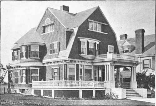
A SHINGLED COTTAGE. (For floor plans of similar bouses see back part of this book.).
Plate 14. Fig. 38 represents the rafters of a pitch roof. Fig. 39 represents the rafters of a hip roof. If the rafters on a pitch roof are 2 x 6 inches, the}' should be notched for the plate so as to leave the rafter 4 or 4 1/2 inches at the narrowest point; then measure the perpendicular width at this point, as indicated by the line A a. Subtract this amount from the rise of the roof, and it gives the rise to use in getting the bevels for the rafters as described in Fig. 35, Plate 13.
In framing the rafters for hip roofs, Fig. 39. there is not usually so much stock in the rafter above the plates as there is in rafters for pitch roofs; the lower end of the rafter being dropped in order to have sufficient stock to form a crow-foot.
1 The lengths and bevels of braces may be found in a similar manner. Suppose the run is 36 inches by 48 inches, \vv may take any fractional part of the run on the square, say, for instance, one-third, which will be 12 inches on the tongue, and 16 inches on the blade of the square: then three times the disgonai thes chtained will be the length of the brace.
Plate 14.
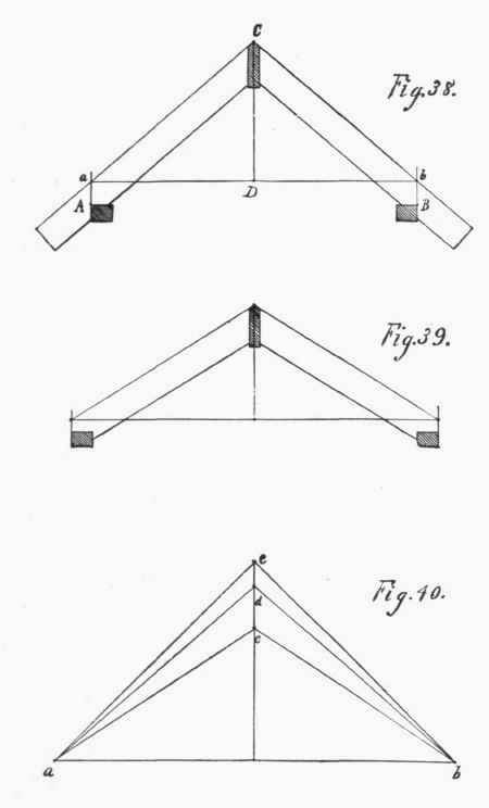
Fig. 40 shows the three pitches in common use. The pitch at e is called the square pitch, the slant of one side of the roof being at right angles to the slant of the other side, the pitch of the roof being 45 degrees. The pitch at d is § pitch, the length of the rafters being § of the width of the building. The pitch at c is called 1/3 pitch, the rise being 1/3 of the width of the building, + There is also the Gothic pitch where the length of the rafters is equal to the width of the building.
Plate 15 shows the method of getting the lengths and rinding the bevels of rafters for hip roofs. Fig. 41 is the elevation of the roof, a b being the width of the building, and e d being the rise of the roof; a d and b d are the length of the common rafters, the bevels of which are found in the same manner as the bevels of rafters for pitch roofs.
Fig. 42. - a b c d is the plan of the building; ef is the plan of the ridge-piece; a f, bf, c e and d e, is the plan of the hip rafters. Draw the line g h, the length of the common rafter a d, square with the line a c; and, passing through e, join c and h, which gives the length of the hip rafter; draw the line op through h parallel to ef; the edge bevel of the hip rafter is shown at h*and the edge bevel of the jack rafters is shown at j; the lengths of the jack rafters are m n, k I, and ij, the down bevels being the same as the clown bevels of the common rafters.
Continue to:


My Books

