


Plates and Illustrations. Part 3
Description
This section is from the book "Modern Carpentry And Building", by W. A. Sylvester. Also available from Amazon: Modern Carpentry And Building.
Plates and Illustrations. Part 3
Plata 6

This method is used when part of a piece of turned work is to he six or eight squared, and the distance across the squares is given.
Plate 5. Fig. 15. To construct an octagon from a square. - Let a, 5, c, d, be the given square. Join a and d. With c for a centre, and a radius tangent to this line, describe an arc intersecting the sides of the given square. Then, with the points a, b, and d for centres, and with the same radius, describe other arcs in the same manner. Join the points of intersection as shown in the cut. The result is the required octagon.
Plate 6. Fig. 16. On a given diagonal to construct a square. - Let a b be the given diagonal. Bisect ah (see Plate 1, Fig. 1), getting the line c d. Take the point of intersection, e, for a centre, and with a radius equal to a e, cut c and d. Join a d, c b, a c, and db, and we have the required square.
Plate 6. Fig. 17. To inscribe a circle in a triangle; also to describe a circle around a triangle. - To inscribe a circle in a triangle, bisect any two of the angles (see Plate 1, Fig. 2), continuing the bisecting lines until they meet, which point is the centre from which to strike an inscribed circle.
Plate 7.
To describe a circle around a triangle, bisect any two of the sides, continuing the bisecting lines until they meet, which point is the centre from which to describe a circle around the triangle.
Plate 6. Fig 18. To inscribe an equilateral triangle in a circle. - Through the centre of the circle, draw the vertical line a b. With b for a centre, and a radius the same as used to describe the given circle, describe an arc intersecting at d and e. Join a d, a e, and d e, which forms an inscribed triangle.
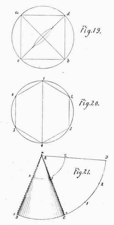
Plate 7. Fig. 19. To inscribe a square in a circle.
- Through the centre of the circle, draw the line a b at an angle of 45 degrees. (See Plate 8, Fig. 22.) Bisect this line, producing the line c d. Join ad, c b, a c, and d b, which forms the inscribed square.
Plate 7. Fig. 20. To inscribe a hexagon in a circle.
- The radius used to describe the circle will space around the circumference just six times: and, by joining these points, the required inscribed hexagon is formed.
Plate 7. Fig. 21. To describe the envelope of a cone. - Let A be the apex of the cone, and B C be the base. The rule commonly given is, to use A for a centre, and with a radius of A C describe an arc, as shown at C D. Then, with the radius used to describe the plan of the base, - the diameter of which is B C, - lay off six spaces. (The cut, for lack of room, shows only half of them.) Draw lines joining the first and the last of these spaces to A.
This is not exact. Lay off on each side of the cone the thickness of the envelope, which gives a b c, which is to be considered as the cone. Then, with a for a centre, and a radius of a c, describe an arc the same as previously described. Then find the circumference of the base of the cone, the diameter of which is b c. This is found by multiplying the diameter b c by 3.1416, or 3 1/7. This length is to be measured around the curve of the base of the envelope, which determines the length of the envelope. Then join these ends to a, which gives the form of the envelope.
If the cone is truncated, that is, the top cut off, as shown at x y, then y z shows the top of the envelope.
Plate 8. Fig. 22. We give here a scale of degrees, commonly called a Protractor, which we believe will be found quite convenient. The various mitres and angles may be taken from this protractor by placing a bevel with the stock on the line, as shown in the cut, and running the tongue from the point a to the number of degrees required. The degrees continue on from 90 to 180; although we have not divided or numbered them, as we have those from 0 up to 90.
The angles of an equilateral triangle are 60°; the mitre is 30°. The angles of a square figure are 90°; the mitre is 45°. The angles of a hexagon are 120°; the mitre is 60°. The angles of an octagon are 135°; the mitre is 67 1/2°.
The sills of window-frames are usually set at an angle of 10 degrees. A few builders set them steeper. We have seen some set at an angle of nearly 20 degrees.
Plate 9. Figs. 23, 24, 25, and 26, illustrate different methods of splicing timbers. Fig. 26 is a keyed diagonal splice, the shoulders being cut square with the slant of the splice. The shaded part is a hard-wood key.
Fig. 27 is bridging for floors. Common strapping 1x3 inches is generally used; although for heavy floors l 1/4x3 or 4 inches may be used, being fastened with two good nails at each end.
Fig. 28 represents two timbers tied together, and supported by a braced post. The notching in the post and timbers for the braces should be cut square with the slant of the braces, as shown in the cut.

A FINE MODERN RESIDENCE. (For floor plans of similar houses see back part of this book.)
Plate 8.
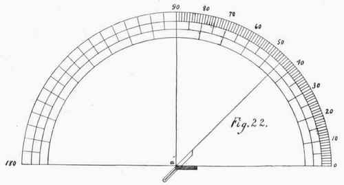
Plate 9.
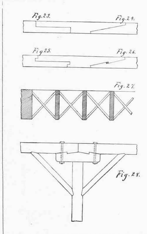
Plate 10.

Plate 10. Fig. 29 shows a plan for floorings. The timbers are usually gained into the sills 2 inches, and down 4 inches, so as to bring the top of the timbers even with the top of the sills. The plan shows an opening for stairs. The headers b b, and the trimmer a, which is also shown in Fig. 30, are made of extra thickness: where the floorings are 2 inches thick, the headers and trimmer should be 3 inches thick.
Continue to:


My Books

