


Plates and Illustrations. Part 5
Description
This section is from the book "Modern Carpentry And Building", by W. A. Sylvester. Also available from Amazon: Modern Carpentry And Building.
Plates and Illustrations. Part 5
* First back off the upper edge of the hip rafter, then use this bevel. The rafter will not fit if this bevel is used before the rafter is backed off.
+ We believe this is the proper method to designate the pitch, instead of the other method.
Plate 15.
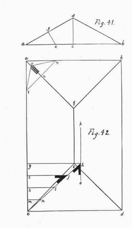
To find the down bevels for the hip rafter, Plate 16, Fig. 43, make a h equal to the length of the plan of the hip rafter (af, Fig. 42), and make g h equal to the rise of the roof, cd; join a and g, which gives the elevation of the hip rafter:-the bevel for the foot being shown at a, and the down bevel for the top being shown at g.
To find the backing of the hip rafter (that is, the amount necessary to chamfer the top edge), take any point on the line a b, Fig. 41, as e; draw a line through this point, square with the slant of the roof, as seen at ef. Take the distance from a to e (Fig. 41), and lay it off from a to 1/8, and from a to s (Fig. 42). Join r and s. Take the distance from e to f (Fig. 41), and set it off from t to u (Fig. 42). Join r u and s u; then rus is a section of the roof cut across the corner at r s, and cut down square with the slant of the roof, as seen at ef (Fig. 41). Now lay off the thickness of the hip rafter, equally each side of the line t a, and we have the shape of a section of the hip rafter; and the amount necessary to chamfer may be seen, or a bevel may be set at the angle formed by the lines u r and u t.
In getting these bevels, the work may be drawn to the scale of 1 1/2 inches to the foot, each 1/8 inch representing one inch of the work.
If the hip roof is placed above a French or mansard roof which tumbles in, then the drawing of the plan of the hip roof must be made of the size of the upper plates, instead of the size of the building.
Greater accuracy is obtained by figuring out the lengths of the hip and common rafters. To find the length of the common rafters, square half of the width of the building; also square the rise of the roof; add together these two amounts, and extract the square root (see the mathematical part of this book): the result is the length of the common rafter. To find the length of the hip rafter, square the length of the common rafter; also square half the width of the building; add together these two amounts, and extract the square root: the result is the length of the hip rafter, on the centre line, as seen at a h, Fig. 44. From these lengths half of the thickness of the ridge-piece must be deducted in the manner before described. The dimensions should be taken in inches. This ride to figure out the lengths applies only to square buildings, and where the pitch of the roof is the same on all sides. Where the buildings are not square, then draw a plan of the whole roof, and find the lengths and bevels of the hip and jack rafters for each of the different corners, as described in Fig. 42.
Plate 16.
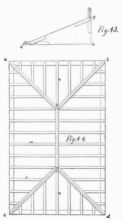
Plate 16. Fig. 44 shows the framing of a hip roof. The centre lines in the hip rafters and in the ridge-piece are the lines representing the plan of the hip rafters and the ridge-piece in Fig. 42, Plate 15. For convenience of fastening the hip rafters to the ridge-piece, this piece is made two or three inches longer at each end than hj, and the rafters n n are cut as much short of their whole length as the ridge-piece extends beyond h or j; the ridge-piece being scarfed from the points h and j, to the pitch of the rafters, n n.
Plate 17 shows the method of getting the lengths and finding the bevels of rafters for valley roofs. Fig. 45 is an elevation of the roof; a b is the width of the building, c d is the rise of the roof (see Plate 14, Fig. 38, deduct a A from the whole rise, and then consider C D as the rise); b e is the rise of the cross roof, and f e is the ridge of the same. The bevel for the foot of the common rafters of the main roof is seen at b; at d is seen the down bevel for the top of the common rafters, and for the top and bottom of the jack rafters, 4 5, and 6 w.
Fig. 46. - a b c d is a plan of the roof; ef is the ridge of the main roof; g h and ih is the plan of the long valley rafters; j k and l m is the plan of the short valley rafters; z m and k p is the plan of the ridge of the cross roof. Lay off from d to n the length of the common rafter a d (Fig. 45); draw the line n o parallel to ef; then from h - the point where the plan of the valley rafter joins the ridge - draw the line o h square with the line ef; join o and g, which gives the length of the long valley rafter, the edge bevel for the top being shown at o. Draw a line from j to k 1, the point where the line o g crosses the ridge zp; then jk 1 is the length of the short valley rafter, the edge bevel for the same, where it butts against the long valley rafter, being shown at k 1. The length of the jack rafters is seen at 4 5, and 6 w, the edge bevel for the same being shown at w. To find the down bevels of the valley rafter, take the plan of the valley rafter i h for a base line; from h draw the line xh; square from ih, making xh equal to the rise of the roof c d (Fig. 45); join i and x, which gives the elevation of the valley rafters, the bevel for the foot being shown at i, and the down bevel for the top being shown at x. To find the length and down bevels of the rafters for the cross roof, take g p for a base line; draw the line p r at right angles with p g, equal to the rise of the cross roof e b (Fig. 45); join r and g, which gives the length of the common rafters (when there are any, as when the building is made in the form of a cross, +); the bevel for the foot of the common rafters being shown at g, the down bevel for the top of the common rafters, and the top and bottom of the jack rafters, being shown at r. Lay the length of the common rafter g r from g to s; draw s t parallel to p k; draw the line t k from k, square with the line kp; then draw a line representing the valley rafter from g through the point t; then the length of the jack rafters is shown at 1, 2, and 3 v, the edge bevels for the same being shown at v. The lengths of these rafters are measured on the centre line of the edge; and from these lengths, half of the thickness of the ridge-piece, or half the thickness of the valley rafter, must be cut off, as may be necessary; the amount to be cut off must be measured square from the bevel on the end of the rafters, so that if the ridge-piece was two inches thick, the piece which would be cut off would be one inch in thickness.
Continue to:


My Books

