Section VI. Erecting Engines
Description
This section is from the "The Construction Of The Modern Locomotive" book, by George Hughes. Also see Amazon: The Construction Of The Modern Locomotive.
Section VI. Erecting Engines
We have well-authenticated instances of rapid erecting, but it is not the author's intention to describe one of these. From 40 to 45 hours is a reasonable tune for erecting engines of the class shown in the sectional drawing. This may be accomplished by a system which gives each chargeman three pairs of frames under his care, and then by a judicious manipulation of his men, engines may be built very much cheaper than if there was only one set of frames for him to superintend. It also must be understood that every other department of the works is at least the greater part, if not the whole of one order in advance of the erecting. The accuracy and system maintained in these other departments is also a factor much in favour of cheap and rapid erecting, which is supplemented by like care in this shop, introducing anything to minimise time or labour, and keeping all templates and gauges up to standard.
In the following figures, some of the necessary helps to erecting may be seen: - Fig, 297 shows two forms of a bottle-jack stand, upon which the frames are erected; Fig. 298, the standard distance stays, which are placed between the frames in suitable and convenient places; Fig. 299, the bit or rimer for opening out the holes in the frames for the cylinders, etc, by the aid of the Stowe flexible drilling shafts; Fig. 300, a light template cylinder cover, which by the help of a 3-inch piece of tube 8 feet long, in conjunction with Fig. 301, is used for setting the slide liars; Fig. 302 is a light template for setting the reversing shaft brackets; Fig. 303 is a late of the standard journals, to which all the axle-boxes are bedded; this saves hunting up treaties and getting roller pins to slide, and eventually lifting a heavy box on to a journal; and Fig. 304 is a half-portion of the cradle upon which the driving wheels rest, to facilitate turning when Betting the valves. These will he referred to again, in due course, in their proper places.

[To face page 224].


Fig. 297.
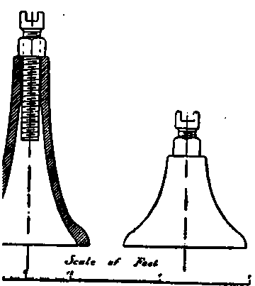
Fig. 298.

Fig. 299.

Fig. 300.

Fig. 301.


Fig. 303.
The progress of erection is illustrated by the four Figs. 305-8, each of which shows the work done at the end of its period; so by tracing the figures representing the second, third and fourth periods, and placing them all upon the first, an almost complete drawing of the engine can he formed. Those portions not shown are the last to go together, so that the whole work dene in the last period can he gathered from the sectional drawing, which shows the engine complete for trial. These illustrations have the advantage of showing very concisely the work accomplished during a certain stage, which is also neither cramped, confused nor minimised by that done during any other period. Each of these figures will he described separately, and the author will take each portion of the work upon the supposition that he is the only mechanic employed, assisted by an apprentice and necessary labourers; whereas in actual practice many operations go on simul-taneosly, in fact as many as possible so long as the pit is not crowded with men, and they do not hinder each other.
Fig. 305
The frames are received in the erecting shop with all sharp corners filed off and all necessary holes tapped. They are first laid upon trestles, and the various centre lines set out for brackets, stays and motion. They are then reared on to the stands, Fig. 297, the first one being cramped to a trestle, or dropped into fork stands, and then temporarily stayed to the other with the standard cast-iron stays, which have been turned up at the ends to dead length, Fig. 298. By the aid of the bottle-jack stands, the frames can be adjusted to height and set square with each other by diagonal trammelling, from the centres upon the top of the frames, over the driving and trailing horns, and also set level, length and crossway, by a straight-edge and spirit level A thin cord is also placed round them at a given distance, to prove that each frame is perfectly straight along its whole length. This cord is not shown in Fig. 305. All platform angle irons, gussets and other supports, which are clearly shown in the figure, are bolted up, the holes opened out by the flexible shaft, and afterwards riveted up by the hydraulic riveter; or, as in the case of supports, cold rivets are put in a driving fit, which are the most trustworthy, especially for the motion plate. The horn blocks are then fitted into the horns, and the holes in the frames opened out. It may be beneficial to remind the reader that these and all other mountings for the frames, including cylinders, etc, have been drilled to standard, consequently they act as drilling jackets to the frames. The horn blocks are secured by turned bolts, a driving fit. The inclination of the cylinders is 1 in 10.


Fig. 306
The temporary angle irons A with their adjusting screws are fixed, and the cylinder casting then lowered on to them. The templates B and C are then placed at the front end and in the driving horn, at given distances from the top of the frames, by the aid in the latter case of a straight-edge across the top and a T square. A long-distance template is then passed through the cylinders to the centre of the driving horn, which gives the distance from that point to the face of the cylinder. Piano wires are then stretched from B to C, at given distances from the inside of the frames, which also fixes the centres of the cylinders. On the template C are thumb-screws, by which the wires are made quite taut and straight. The cylinders are then set to these lines, and securely fixed by temporary holts. The motion plate is then fixed to distance by a template, which fits in the holt holes of the lugs on the cylinder for the slide bars, and also in those upon the motion plate. It is set by the aid of a straight-edge across from the lugs on the stuffing-box and the brackets on the plate. The template covers, Pig. 300, are now fixed to the front end of the cylinders, and the slide bars set by passing a 3-inch tube through, about 8 feet long, which has a bearing in the cover and gland. The template of the slide blocks, Fig. 301, must work up and down quite freely, but at the same time it must be absolutely free from all shake.
Continue to:
My Books

