Erecting Engines. Part 2
Description
This section is from the "The Construction Of The Modern Locomotive" book, by George Hughes. Also see Amazon: The Construction Of The Modern Locomotive.
Erecting Engines. Part 2
The use of this tube and template renders the operation a certainty, and is fully appreciated by the operator after a trial. A straight-edge smeared with a very thin film of red lead is also tried over the whole set to get them square, or in the same plane with one another. There is a suitable liner placed under every bearing of the slide bars, to allow for taking up wear and tear. The cross or frame stay is then set to a centre line, which has been fixed at the right distance from the driving horn. The foot or drag-plate is set level with the hinder portion of the frame, flush and square with the end. All having been securely fixed with temporary bolts, it is then the foreman's duty to pass the whole, as he must be absolutely certain that everything is correct before anything else is proceeded with. He first walks round the frames, passing his gauge at intervals between the frame and the cord D, to ascertain the correctness of the straightness of the frames, or that they are parallel. Next, he tries if they are level, both longitudinally and transversely, also if the diagonal measurement between the driving and trailing bonis is correct. He then ascertains that the templates B and C are fixed at their proper distances from the top of the frames. The face of the cylinder has been planed to a given distance from the centre of the ports, and a template has been made to ascertain the correctness of this, so that the next operation, verifying the distance from the centre of the driving axle to the face of the cylinder, shall not be nullified by any mistake on the part of the planer. He next tries the distance of the piano wires from the inside of the frames, which proves that they are parallel, also that the distance from the centre of the cylinder to the planed frame seating of the casting is correct.
The insides of the cylinders are then gauged from the centre wire at the front end, also at the stuffing-box, and finally a spirit level is placed upon the smoke-box tube plate seating. All the holes are then opened out by the rimer, Fig. 299, and the Stowe flexible shaft, which is shown in position at the back end of the frames. Turned bolts or rivets, as the case may bo, are then driven in and all secured. The platform edge angle irons and plates are then fixed and riveted by hydraulic riveters. The slide valves and buckles are then placed in the steam chest, a 3/16 inch liner being put into the front port and the edge of the slide valve pushed up against it; this position is then indicated upon the valve spindle by trammelling a short length from the back of the cylinder casting on the spindle. This liner is then placed in the back port and the edge of the valve drawn up against it, the same trammel length marked upon the spindle, which gives the position of the valve at the commencement of the stroke or lead. The pistons and rods are then put in, and the "bump" or clearance marked on the slide bars for each end, and then everything is boxed and bolted up, a temporary cover being placed over the exhaust.

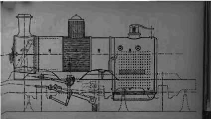
Fig. 306.
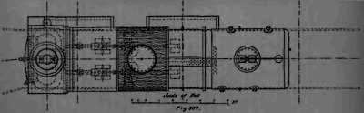
Fig. 307
The work of this period is commenced by fixing the brackets for the reversing shaft, which is only temporary, the final fixing taking place after the setting of the valves, because this shaft bears a most important relation to the position of the valves. They are bolted in their places temporarily, being set by gauges from the centre of the driving horn and from the top of the frame. The template, Fig. 302, is used instead of the shaft itself, because of the great weight of the latter, and consequently if the template is a good fit, square and turns freely, the shaft can be depended upon to be the same. The connecting-rods are then coupled up to the cross-head, the big ends (minus their straps) resting on baulks of timber, or better, slung from the top of the frames. The reversing shaft is then lifted into its brackets and the rest of the motion is fixed and pinned up. The boiler which has been mounted, see p. 34, is now placed in position and secured at the smoke-box end by nine ⅞ inch bolts, turned and of driving fit, the tube plate resting upon its support, which is a portion of the cylinder casting. The fire-box end is fixed by the expansion angle iron, Fig. 38, p. 24, and then the distance of the centre line of the boiler is gauged from the top of the frames by a standard gauge.
The accuracy which has been attained in constructing the boiler is such that there is never any necessity for it to be lifted out of the frames because the expansion angle iron was not square, or that the tube plate would not drop on to its seating. In works where these errors occur endless trouble is caused, because the angle iron, if not square, must be chipped upon the under side, from nothing at one end to the required amount at the other, to bring it true. The tube plate must be warmed by heaters and set back or forward, as the case may be. Frequently one or two trials and various chippings have to be made, which in the aggregate make up a loss of time at the least estimate of ten or twelve hours, one of our periods or thereabouts, and then finally it is not a good job. The boiler is then lagged with red dual dipped in limewash, which is as good as yellow pine painted with asbestos, and clothed with sheets 14 I.W.G. In the meantime the fire bars have been put in, and the ashpan cottered up to the foundation ring. The smoke-box is then built and riveted up, all rivets being counter-sunk, chipped, and filed flush with the outside case. The steam pipes are then fixed, also the blast pipe, the centre of which is a given distance from the front of the tube plate. This forms the centre of the chimney, which is set square with the boiler and plumb with the centre of the exhaust. The leading splashers, which are in one easting with the leading sand-boxes, Figs. 69-72, p. 64, are then adjusted, and also the driving splashers. The work to be done at these is very little; excepting the fixing and bolting down, little or no fitting is required. During the fixing of the wood lagging the axle-boxes are bedded, also the big end brasses, the template, Fig. 303, being used for the boxes, and then each of these is mounted on the axles. The axle-boxes are bored out a quantity at once, on a machine with horns, the boring bar of which slides out. They are dropped into these horns consequently when bored the centre of the radius of the crown is equidistant from each horn seating. They are then tried up in the horn blocks, simply to adjust the horn wedges.
Continue to:
My Books

