Moulding. Part 2
Description
This section is from the "The Construction Of The Modern Locomotive" book, by George Hughes. Also see Amazon: The Construction Of The Modern Locomotive.
Moulding. Part 2
Figs. 146-148 give views of the slide valve, the importance of which has already been demonstrated, especially relating to the metal from which it is cast. By adopting the following method of moulding the slide valves, all necessity for machine work upon these castings, with the exception of grinding the faces over, is dispensed with, which reduces their first cost considerably. The exact thing is not arrived at all at once, but after a few trials and a knowledge of the behaviour of the mixture, the patterns can be so regulated that the shrinkage will be sufficient for the resulting casting to fit the standard gauges. If the mixing should be changed (which is very seldom when once a good working one has been obtained, economical in wear and other points), the patterns would have to be lined up, or dimensions reduced, according to the amount and direction of contraction. The pattern, which is metallic, is placed upon the plate A, which is a good fit in the plate B, but slightly thinner, each plate having suitable dowels, Figs. 149 and 150. They are placed on a turnover board, the top and bottom boxes rammed Up and vented, the print of the pattern being in the top box. The plate A being slightly thinner than the plate B, the flange of the pattern just enters, consequently when the bottom box is removed and the plate A drawn, the pattern can be drawn upwards through the plate B with a minimum amount of swelling to the mould. The core for C, Figs. 147 and 148, is formed by ramming up that space in the pattern and joining it to the bottom box, through the plate B, the casting being of phosphor bronze. The radius or slipper blocks for Joy's valve motion are also of phosphor bronze, the patterns of which are shown in Figs. 151 and 152, the half with the short core print being placed in the bottom box, well vented in the top and slightly in the bottom, and run at the joint at A. The lightening core B, Figs. 151 and 152, is given in Figs. 153 and 154, and the oil syphon C, Figs. 151 and 152, in Figs. 155 and 156.
Fig. 126.
Fig. 127.
Fig. 128.
Fig. 129.
Fig. 130.
Fig. 131.
Fig. 132.
Fig. 133.
Fig. 134.
Fig. 135.
Fig. 136.
Fig. 137.
Fig. 138.
Fig. 139.
Fig. 140.
Fig. 141.
Fig. 142.
Fig. 143.
Fig. 144.
Fig. 145.

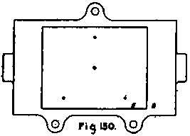

Fig. 151.

Fig l52.
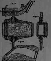
When the axle-boxes are not cast in steel or iron, Figs. 157-162 show the patterns and core-boxes for the brass foundry. The core print A is placed upon a turnover board, and the joints made at B and C, Fig. 157. The metal strips, Fig. 159, are bevel pieces let into the sand to form the corners at the top of the box, where it enters the horn. Fig. 160 is the core-box for the oil syphon and tallow receiver, and is suspended by a wire from the outside of the top box to the core iron, and fitting into the core print A. Figs. 161 and 162 are two views of the core-box for the white metal recess, and correspond to the core print D. The casting is run by two branches from each of two leaders at the top and bottom of the mould, the leaders being rectangular, 1 1/4 inch by 1 1/8 inch, tapering to 7/8 inch by 3/4 inch. The tender axle-box brass is shown in Figs. 163-168, being top and bottom plans, side and end elevations. The metal strip A, Figs. 163 and 166, enables the pattern to form its own white metal cores. The joint follows the core prints at the sides and the curve of the bearing between, in order to allow of a free draw. The casting is run on to the top of the mould at one end about the middle, see B, Fig. 163, this also indicating the position of the pattern in the box, which is well vented in the top and slightly in the bottom. Fig. 169 is the pattern for the safety valve pillar, and Fig. 170 its core-box, the joint being a diagonal with the bottom square. The scoop for Ramsbottom's water pick-up is shown in side elevation, Fig. 171, the joint being indicated from A to B along the centre of the pattern. Fig. 172 is a plan, Fig. 173 an end elevation, and Fig. 174 its core-box. It is cast in boxes specially adapted for the work; the loose parts held by pegs are rammed up slightly, and then the pegs are drawn. It is run from two leaders at D and C, F and G being core prints to form bearings for the wrought-iron arms which are cast in. Fig. 175 is a finished sectional drawing of the ball-and-socket connection between the tender and the injector, and Figs. 176 - 186 its pattern in detail, which indicates clearly the method of procedure in moulding.
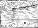
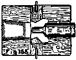
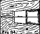
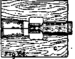

Fig. 158.
Fig. 159.

Fig. 163.
Fig. 164.

Fig. 165.
Fig. 167.
Fig. 169.
Fig. 170.
The No. 8 combination injector is given in Figs. 187 and 187a, its pattern in Figs. 210 and 211, the core-boxes in Figs. 212-217, and patterns of details in Figs. 188-209. It may he observed that the shop pattern number is 2710, and the details range from 2711-2730, so that comparing the drawing with the details, it will at once be seen how they are moulded, The core-boxes, Figs. 212-217, are lettered A to D, and the finished drawing has also the corresponding letters, so that each core can be identified with that portion of the mould.
Fig. 175.

Figs. 176 I77 & I78.
Figs. 179 & 180.

Fig. 181.
Fig. 182.
Fig. 183.
Fig. 184.
Figs. 185 & 186.
It may be considered an opportune moment to describe this injector, as when dealing with it in the machine shop it will then only be necessary to describe the tool work required. The patent rights claiming improved construction are held by Messrs. Gresham and Craven of Sulford, The casing of the injector, along with the flange junction for the boiler attachment, is formed in one piece. The mechanism consti-tilting an injector, viz. nozzles, cones, valves, cocks and other parts, is combined together so as to utilise thin one flange or equivalent connection, having two openings, one for steam and one for water, and fixed to the fire-box front with 004 joint, the openings being each connected with a pipe leading to the points required in the interior of the (toiler.
Continue to:
My Books

