


Horology. Part 10
Description
This section is from the book "The Engineer's And Mechanic's Encyclopaedia", by Luke Hebert. Also available from Amazon: Engineer's And Mechanic's Encyclopaedia.
Horology. Part 10
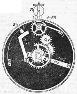
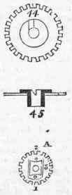
The hour-wheel, marked A, Fig. 2, lies immediately underneath the alarum wheel, and has on its under side an oblong steel plate, 1, 2, 3, in the detached figure A of Fig. 2, which is called the detent. The detent is spring-tempered, has a hole in its centre for the free passage of the cannon arbor, and is fixed flat upon the hour-wheel by a small screw and steady pin at 2; into the opposite end of the detent plate at 1, is rivetted a small pin of sufficient length to pass through a hole in the hour-wheel, and to project beyond the upper surface of the same in such manner, that when the hour-wheel and the alarum-wheel are put together in their right places, and this pin presses upon the flat surface of the steel plate 44, the end 1 of the detent is depressed below the under face of the hour-wheel, but when it comes over the notch it falls into the same, and allows the end of the detent to rise and lie flat in the recess in the hour-wheel. T L end 1 of the detent acts upon the circular end 2 of a flat steel spring C, Fig. 1, and shown detached in the following page; it is called the elevator, and is fixed in its place by the screw and steady-pin at Z, which end is thicker than the other parts of the spring, so that the end 2 is raised above the plate on which it is fixed; the degree of elevation may be adjusted by turning the screw-top at y, which works freely through a hole in the elevator.
The end 1 of the detent presses upon the elevator in such manner, that whilst the detent is depressed it holds down the end 2 of the elevator; but so soon as the pin in the detent enters the notch, and the detent rises, the pressure is withdrawn from the elevator, and it likewise rises to discharge the alarum, which it does through the medium of another piece called the propeller, drawn in its proper place and form at D, Fig. 1, and also shown in the detached figure in the margin. It is a steel lever without spring, and turning upon the screw x as a fulcrum; it has a projecting piece W, which is formed into an inclined plane, and highly polished and hardened; this inclined plane falls directly under the end 2 of the elevator C, also polished at this part; consequently, whenever the elevator is depressed by the detent, its end 2 will press upon the inclined plane W of the propeller, and drive it's end V outwards; this end is formed into a portion of a circle not concentric with x, and presses against the locker E, Fig. 1, which is a cylindrical piece of steel, having in its outer end a small pin s projecting through the case of the watch; the locker E moves between two pins, and is pressed against the end of the propeller D by the spring F, and kept at all times in contact with it.
The combined effect of the several parts may be briefly recapitulated as follows: - whilst the detent is depressed, it presses down the circular end of the elevator c, which acting upon the inclined plane W of the propeller D, forces its circular end against the locker E, and causes its small pin s to protrude beyond the case, in which state it will remain until, by the revolution of the hour-hand, the pin in the detent falls into the notch on the alarum arbor; when the elevator rises, and the pressure being withdrawn from the inclined plane of the propeller, the locker E is pushed in by the spring F, and remains in that position until the sloping side of the notch 44 has been moved round sufficiently to depress the detent spring again. The above is all that is necessary to form the union between the going parts of any watch, and a detached alarum, because it will be evident that such alarum may be disengaged or set off by the sudden withdrawal of the locker; we shall therefore proceed to describe the manner in which the alarum movement is operated upon, whether the alarum of the bell, rattle, or any other kind.
Fig. 1.
An alarum movement in its separate state is represented at G H, in the annexed figure, and consists of a frame, the upper plate of which is nearly half an inch less than the pillar plate, in order that the works may be covered by, and contained within the bell, as shown at Fig. 2, which is a section or profile of the alarum movement. A going barrel, which contains the mainspring, is placed in the centre of the said frame, and a steel wheel cut with ratchet teeth to work the hammer is fixed on the upper part of the said barrel, its other side carrying the main wheel to drive the train, which generally consists of three wheels and four pinions. The alarum hammer has a spring and a regulating spring on the opposite side of the plate as shown at K, Fig. 4. The fly pinion has an arm of steel fixed on its arbor, and as this comes in contact with the projecting pin, Fig. 2 the works are locked, and the alarum prevented from running down; but so soon as the pin H is moved, the whole is at liberty, and free to move; the pin H passes through a hole in the plate, and rises from the locking lever H on the other side of the plate, as shown in Fig. 4, where it may be seen that this locking lever turns on a screw pivot at its inner end, and is constantly pressed to one side by the force of the spring P, which operates in such a direction as to throw the pin out of contact with the steel arm of the fly arbor, and consequently always keeps the alarum work in a free state for motion; but it may be locked at any time by pushing the locking lever H, Fig. 4, backwards, or against the action of its spring P; a wire tail, l, rises perpendicularly out of the outer end of the locking lever H, and it is this wire tail that is to be engaged with the small end s of the locker E s, Fig. 1, whenever the alarum is to be wound up and set.
This locking lever H, with its two pins, is here shown in a detached state.

Continue to:


My Books

