


Horology. Part 11
Description
This section is from the book "The Engineer's And Mechanic's Encyclopaedia", by Luke Hebert. Also available from Amazon: Engineer's And Mechanic's Encyclopaedia.
Horology. Part 11
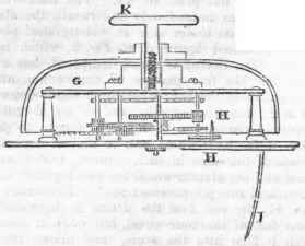
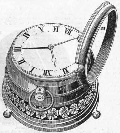
Fig. 5 shows a watch having all the above described parts appertaining thereto, and placed upon one of the aforesaid detached alarum movements; l being the case of the alarum, formed of open-work, chased or otherwise ornamented, and having the appearance, when empty, of the ordinary receptacle of an external watch case; M being the usual rim that shuts down over the watch with a spring catch, and thereby holds it steadily in its proper position; the alarum movement is fixed in this external case, with the pillar plate upwards, and the works and bell downward; consequently, the wire tail l, Fig. 4, projects upwards into the case, and in placing the watch within; it is necessary to observe that the projecting end of the locker s, Fig. 1, comes behind, and engages with this wire tail, as seen at H F, Fig. 5, in such manner, that it may push back the locking lever, li, Fig. 4, and thereby lock the train of the alarum when the rim M is to be shut down, and the alarum hand set as aforesaid to the time upon the dial when it is to be discharged.
The alarum may then be wound up by the key, or milled head K, Fig. 2, which is screwed upon the main spring arbor, so that it can only turn it in one direction without unscrewing, and the machine will be ready to operate; because at the assigned hour and minute, the ends of the locker will be withdrawn into the watch, thereby releasing the wire tail l, and the locking lever H, Fig. 4, by which the alarum will be discharged, and will instantly run down.

What has been said of the bell alarum movement, equally applies to rattle movements, because they consist of the same parts, and are constructed and used in the same manner, except only that the bell, the hammer, and the steel ratchet wheel for working the same, and the springs connected therewith, are dispensed with, and in lieu thereof, the rattle movement, shown in Fig 6, is substituted. This consists of two strong steel wheels N N, so fixed or screwed upon the outside of the upper plate that they may both press in the same direction against the two strong pins or studs q q to receive them, and the upper plate may in this construction be made of the same diameter as the lower plate, because there is no bell to go over it. A coarse steel pinion M is fixed on to a square upon the continued arbor of the first wheel in the movement, and which wheel for this purpose is brought nearer to the edge of the plate, in such manner that the lever of the said pinion may engage with the ends of both the springs N N, and by its revolution may carry them some distance towards r. and on their return they strike against the pins q q, and produce a powerful rattling noise; more or less springs may of course be used for a similar purpose, according to the extent of noise required.
Of late years, the ingenuity of watch-makers has been much exercised in the winding up of watches, without the employment of detached keys; but from the difficulty of applying such an improvement to watches having fusees, their efforts have been solely directed to the winding up of those having going-barrels; and various contrivances have been proposed and adapted to the latter for that purpose. Mr. Berollas, whose patent detached alarum watch we have just been describing, has, however, overcome all the obstacles which the subject opposed to him, and has contrived the means of winding up watches of both construction without keys, by a contrivance exhibiting great simplicity as well as ingenuity. For this invention he has taken out a patent, and from the specification of it we make the following extracts; which, together with the annexed engraved figures, will give the reader a full insight into the arrangement and the mode of constructing this useful improvement. "The first mover, or power, in most horological works, is obtained either by the action of a weight or spring.
In pocket watches, the power is obtained by a spring called the main spring, which is enclosed in a box called the barrel.
Now there are two distinct ways of applying the power of this main spring to the first wheel of a watch; one of them consists in the intervention or agency of a fusee, which is put upon the first wheel; in the other, the first wheel is put upon the barrel itself that contains the spring, which arrangement is distinguished from that having a fusee by the term 'going-barrel.' Watches having going-barrels are wound up by turning round the barrel arbors; and watches having fusees, by the fusee arbors. My invention consists in a new mechanical arrangement, applicable to the winding up of horological works. First, as respects what is termed a going-barrel, the following are the contrivances that l have invented as applicable thereto: Fig. l represents a watch with a going-barrel, to which my invention is applied; in which figure a part of the dial-plate is represented as broken away, for showing the novel parts, the operation of which will be understood by first describing the separate figures, 2, 3, 4, 5, 6, 7, 8, all the same letters of reference in which refer to similar parts.
Fig. 2 is the barrel ratchet with its click and spring, which keeps the maintaining power up; this ratchet is put on the barrel arbor, which is squared, and the plate is sunk in which it lays - it is on the side of that part of the plate under the dial; this barrel ratchet is sunk or turned out as far as the teeth to receive another ratchet with its click and spring, shown at a, Fig. 3, which l call the recoiling ratchet. This recoiling ratchet is fastened on to the barrel pulley 6; the upper side of this barrel pulley is sunk to receive a spring, shown in Figs. 1 and 5, which is the recoiling spring; on the edge of the barrel pulley there is a groove to receive a chain d, shown at Figs. 1 and 8, which is hooked on a pin in the said groove. Fig. 7 gives a perspective view of the stud which keeps the barrel pulley steady and close to the barrel ratchet; the centre of this stud is round, and the centre of the recoiling spring is hooked on to it; the other end of the recoiling spring is hooked on the barrel pulley.
Continue to:


My Books

