


Boiler. Part 6
Description
This section is from the book "The Engineer's And Mechanic's Encyclopaedia", by Luke Hebert. Also available from Amazon: Engineer's And Mechanic's Encyclopaedia.
Boiler. Part 6
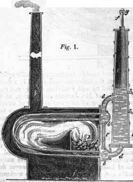
The chambers b have direct communication one with another, by means of the vertical pipes c; d d, are two bent tubes, leading from b b into the steam vessels or "separators" e e (as Mr. Gurney calls them.) From thirty to fifty, (according to the size of the apparatus) of the small pipes a, are arranged in the manner shown in Figs. 1 and 4, in which the fuel is placed as at h, the heated air and flames being directed by a bridge i, to take the course delineated before entering the chimney k; but a considerable portion of the heat passes freely between and round about the pipes, the whole of them being exposed to the powerful effects of a furnace so circumstanced; o is the furnace door, and t the ash-pit.
During the working of the engine, the steam chambers e are by the usual means kept supplied with water up to the level shewn, which being higher than the pipes in the furnace, the latter are always kept full of water, as judiciously recommended by Woolf in his specification, quoted in the preceding part of this article. The steam generated in the small pipes ascends by its superior levity through the water in the steam vessels e, or it may be, transmits its caloric to other particles of water, which escape at the surface of the fluid in the form of vapour, which passes off through the branches f f into a common pipe g, that leads to the engine. In fixed engines the iron casing represented as surrounding the boiler is dispensed with, the apparatus being set in the usual manner in brick-work. To obviate a common objection to tubular boilers, of their becoming choked with a deposition of earthy matter, Mr. Gurney purposes to clean them out when they become foul, by the following chemical treatment.
If the tubes are of iron, one part of muriatic acid, with 100 parts of water, are to be left in the boiler, a sufficient time to dissolve the incrustations; if of copper, the following solution is to be used in a similar way, one pound of common salt, half a pound of sulphuric acid, in four gallons of water. To expedite the operation of cleansing, a small fire may be made in the boiler, and the steam be employed to blow the contents out of the tubes. One of the most prominent advantages attending the use of this boiler, is the great facility with which repairs are executed; when a tube is injured or burned, the removal of it or the substitution of a new one are only the work of an hour. Like other tubular boilers, it is safe from the effects of rupture; but the "separator" being in fact a steam reservoir, that part is as liable to explosion as other boilers of the same capacity and thickness of metal. The small tubes exposed to the fire, if always kept full of water, are not likely to be soon burned out. The merit of this arrangement is however, due to Mr. Woolf, (see page 201,) and were Mr. Gurney's steam reservoirs defended like thai gentleman's, from the cooling influence of the atmosphere, the effect of their contents upon the engine would be improved.
Fig. 3.
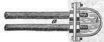
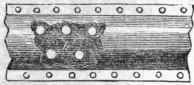
Fig. 4.
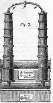
The annexed diagram is explanatory of a boiler which has been employed for the generation of steam in the locomotive carriage of Messrs. Summers and Ogle, who have taken out a patent for it. It consists of a series of tubes, placed vertically, with a flue passing up the centre of each; a a a represents the external tubes containing the water and steam; b b b the interior tubes or flues, for the passage of a portion of the heated air, etc, the remainder passing off between the exterior tubes; and thus the water of the boiler disposed in thin hollow cylinders is continually exposed to an extensive surface of heated metal on both sides, ccc are the ends of the internal tubes passing through the screwed nuts d d d at the top, and e e e at the bottom, and by which both the exterior and interior tubes are secured in their places. The water is supplied to the boiler through the pipe f, by a force pump; and the steam when generated, passes off to the engine, by the pipe i. Although the heated matters from the tire have but a short passage to the chimney, it is obvious that the obstruction to the current formed by so many tubes crowded together must be considerable, and cause a great portion of the heat to be absorbed, it being, as it were, wire-drawn.
Economy of fuel is, however, not a matter of such important consideration in a steam carriage, as in fixed engines; there being in the present infant state of locomotion, on the common road, no competition. It is obvious that the different parts of this boiler can be put together with facility, and that a defective tube can be instantly removed, and a sound one substituted, by simply unscrewing the interior flue or tube. The manufacture, however, requires the utmost exactness, especially in making all the tubes of precisely the same length, and the other parts corresponding with each other of uniform dimensions; otherwise a source of imperfection would arise, from the longer tubes preventing the shorter ones from being screwed sufficiently close to render them steam-tight. Although the inventions of Mr. Jacob Perkins (who has distinguished himself by numerous ingenious attempts to generate and work steam at pressures far beyond that of any other experimentalist or engineer,) have not been attended with that success which the public were led to believe, many of his arrangements possess considerable merit, and ought to have a place in this work.
We allude in particular to his having brought steam of enormous pressure under the most perfect control. The annexed diagram is explanatory of a boiler employed by Mr. Perkins, which we saw working a small engine on the high pressure and expansion principle, calculated by him at 30 horses' power. A series of cast-iron bars. 5 inches square perforated throughout longitudinally, with 11/2 inch circular holes, were arranged in three tiers, A, B, and D, across a furnace, of sufficient length to come through the opposite walls, where their extremities were connected together in a peculiar manner, so as to form one continuous vessel. By the operation of a forcing pump water was continually injected under the pressure of a heavily loaded valve into the two upper tiers of tubes, so as to keep them always full; the third or lowest tier of tubes contained no water, and were to be kept at a temperature of about 1000° Fahrenheit At each stroke of the engine, a certain quantity of the water contained in the two upper tiers, (supposed to have acquired a temperature of 700° or 800°,) was discharged into a valve box at C, communicating with the lowest tier of tubes D, wherein it flashed into steam, and passing successively through those tubes, exposed to the intensity of the fire, it was received into a steam chamber L for the supply of the engine.
Continue to:


My Books

