


Boiler. Part 5
Description
This section is from the book "The Engineer's And Mechanic's Encyclopaedia", by Luke Hebert. Also available from Amazon: Engineer's And Mechanic's Encyclopaedia.
Boiler. Part 5
The first we shall describe is the invention of Mr. W. H. James, patented in 1823. It consisted of a series of annular tubes of equal capacity and diameter, placed side by side, and bolted together, so as to form by their union a long cylindrical boiler, in the centre of which, at one end, the fire-place was situated. The tubes were made of the toughest wrought iron, three sixteenths of an inch thick; and being of only one inch in diameter, they were capable, as was proved, of sustaining a pressure of several thousand pounds per inch. In some of these boilers, the tubes were made square in their transverse section, consequently, when their flat sides were placed together as described, there were no open spaces between them; and the annular tubes were connected together by means of long bolts passing through the end-plates of the cylinder, where they were screwed up firmly by nuts on the outside. Communications from tube to tube were made by making two perforations in them lengthways of the cylinder; one on the upper side, for the free passage of the steam, and one on the lower, for the flow of the water.
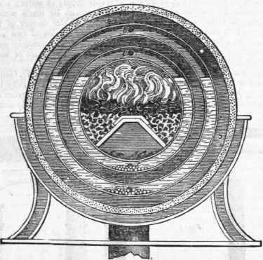
When it was desired to construct a boiler of greater power in a compact form, to adapt it more particularly to locomotion, Mr. James preferred making two concentric cylinders, each composed of a series of annular tubes, like those described, and as delineated in the annexed diagram, which exhibits a transverse section of such a boiler. The annular tubes are distinguished by the water drawn therein. The upper perforations or steam passages are shown at b b, and the lower, or water passages, at c c. The water was maintained at the desired level by the action of a float, in an adjoining vessel, not shown in the figure. The furnace bars formed two inclined planes, as shewn, at one end of the cylinders, and the flue descended at the other end. These latter parts were made so as to be easily detached at pleasure. The entire boiler turned upon an axis, and rested upon rollers, fixed in a circular stand; every tube was furnished with some shot, mixed with angular pieces of metal, so that when it was desired to cleanse the boiler of deposit, the furnace and chimney tube were drawn out, the connecting pipes unscrewed, when the cylinder was turned round by a winch, in the manner of the common scouring barrel, used for brightening metallic articles To prevent the loss of heat by radiation, the boiler was surrounded by a double case, the spaces between which were filled up with a mixture of clay and charcoal.
We have repeatedly seen a boiler of Mr. James's construction, on the principle of the last described, but consisting of only one cylinder of annular tubes, 3 feet 6 inches long, and 20 inches diameter, effectively working a very small high pressure engine, (having only a 3 inch piston of 12 inch stroke,) up to three horses' power.
This boiler had circular tubes, and each annulus was made out of two semicircular pieces, connected at their extremities to an upper and a lower transverse horizontal tube, the length of the cylinder; the upper one forming the principal and the connecting steam tube, and the lower one the water tube. Into these horizontal tubes, conical perforations were drilled, to receive the extremities of the semicircular tubes to which they were united, steam and water tight, by means of bolts and rivetted keys. However firm this mode of uniting appeared to the eye, and however accurate the workmanship, when the fire came to act upon the joints they often became leaky, and were the source of great trouble and inconvenience. Since the period alluded to, Mr. James has invented another boiler, to which he gives the preference, and will be described under the article Steam. Before, however, we quit this part of the subject, we would draw the reader's attention to the circumstance of the steam chambers in Mr. James's boiler, as shewn in the preceding engraving, by which it is evident that the surfaces of the water are pressed upon by the steam, and that the latter derives an increase of heat and of elasticity subsequently to its formation, by the action of the most intense part of the fire; consequently it would appear that this arrangement is eminently calculated to prevent the water rising, or being forced over into the engine; an inconvenience which had been experienced in most boilers made of small tubes. Although the inconvenience never occurred in Mr. James's boilers whilst the fire was kept steady, the supply of water regular, and the tubes clean; yet from the neglect or failure of some one of these conditions, the water did occasionally come over. The observations we have been enabled to make upon these facts, incline us to the opinion that it would be better not to make boilers of tubes of a less diameter than two inches; because the much larger body of water such contain are not so suddenly and violently affected by ordinary variations of temperature occasioned by unskilful firing, or by the irregular supply of water; nor are the tubes so liable to become choked, as the joints can be made with greater accuracy without filling up the water or steam way, to the danger of the tubes becoming red-hot, and the destruction of the boiler.
Tubes of two inches can be much more easily cleansed; and as respects safety, it is scarcely possible to burst them, if only a quarter of an inch thick, by any pressure of steam that can be beneficially applied.
The contrivance we shall next notice is the invention of Mr. Goldsworthy Gurney, a gentleman of. the medical profession, but more generally known to the public by his persevering attempts for the establishment of steam carriages on the common road: and the boiler we shall describe is especially designed for that purpose. Fig. 1 shows a vertical section of the boiler. Fig. 2, an external end view of the same. Fig. 3, the manner in which the series of pipes composing the boiler are fixed, and open into horizontal chambers. Fig. 4, a portion of one of the horizontal chambers, partly broken away to exhibit the apertures of the pipes, and their arrangement. The same letters on each figure refer to corresponding parts. In the section Fig. 1 the semi-elliptical form in which the pipes are bent, and the manner in which they respectively cross each other, is seen; the ends of these pipes have screw threads on the outside, to receive nuts, which secure them to the horizontal chambers b, as shown in Fig. 3; a packing composed of pounded asbestos, mixed with red lead and litharge, in about equal parts, is interposed between the nuts and the end plate, applied in hollow washers of a saucer-like form, which it is said makes perfectly steam, water-tight, as well as fire-proof joints.
Continue to:


My Books

