Modifications Of The Still-Head. Part 5
Description
This section is from the book "Distillation Principles And Processes", by Sydney Young. Also available from Amazon: Distillation Principles And Processes.
Modifications Of The Still-Head. Part 5
Bulb Still-Heads
A vertical tube with a series of bulbs blown on it was recommended by Wurtz.1 For a given diameter of tube and bulbs, the greater the number of bulbs the higher is the efficiency, but the greater also is the quantity of liquid and vapour in the still-head (Table 51).2
The tube with thirteen bulbs was somewhat more efficient than the slightly shorter tube with rod and discs, but the quantity of liquid and vapour in the still-head was half as large again.
Table 51
Nature of still-head. | 3 bulbs | 7 bulbs | 13 bulbs | "Pear" still-head, 13 bulbs |
Vertical height in cm. | 26 | 42 | 66 | 62 |
Final temperature. | Percentage weight of distillate. | |||
83.2°..... | ... | 0.2 | 1.4 | 3.0 |
86.2..... | 2.2 | 14.2 | 24.4 | 26.2 |
89.2..... | 18.8 | 18.0 | 10.2 | 11.0 |
92.3..... | 18.4 | 12.0 | 7.9 | 5-8 |
95.4..... | 9.4 | 51 | 6.0 | 5.2 |
98.5..... | 7.8 | 6.4 | 3.7 | 2.4 |
101.6........................................ | 6.7 | 4.6 | 3.6 | 2.4 |
104.6..... | 5.8 | 4.8 | 3.4 | 2.8 |
107.6......................................... | 6.4 | 5.6 | 3.4 | 3.6 |
110.0..... | 8.0 | 6.2 | 6.2 | 5.0 |
110.6......................................... | 10.0 | 10.4 | 8.0 | 11.0 |
Pure toluene by difference | 6.5 | 12.5 | 21.8 | 21.6 |
100.0 | 100.0 | 100.0 | 100.0 | |
Weight of liquid and vapour in still-head | 0.95 | 1.75 | 3.55 | 2.6 |
The "Pear" Still - head. - The "Wurtz" still-head may be improved, to some extent in efficiency, but chiefly as regards the quantity of condensed liquid, by blowing pear-shaped instead of spherical bulbs on the tube (Fig. 43).
As a result of this alteration, the condensed liquid in any bulb, after flowing past the constriction, instead of spreading itself over the inner surface of the bulb below, mixing with the liquid condensed in that bulb and flowing down the sides with increasing velocity, collects on the depression in the bulb below and falls in drops near the middle of the bulb. The liquid on the inner surface of each bulb is merely the small amount condensed in that bulb, and its velocity of down-flow is no greater in the bottom bulb than in the top one. The liquid, on the other hand, that collects on a depression (that is to say, the total quantity condensed in the part of the still-head above it) is brought well in contact with the ascending vapour in a part of the bulb that is less exposed to the cooling action of the air than any other. It is probable also that the eddies in the vapour are greater than in the ordinary bulb tube.
1 Wurtz, " Memoir on Butyl Alcohol," Ann. CMm. Phys., 1854, [III], 42, 129.
2 Neither the experimental results obtained by Kreis * nor the conclusions he deduces from them can be accepted, for he obtained a very much worse separation of benzene with four bulbs than with two, though the separation of toluene was better. It was, however, according to his figures, not so good as with an ordinary distillation bulb.
* Kreis, "Comparative Investigations on the Methods of Fractional Distillation," Liebigs Annalen, 1884, 224, 259.
The "pear " still-head is more efficient than the "rod and disc "tube of the same length and possesses the same advantages except that it is somewhat more difficult to construct. It may be especially recommended for liquids of high boiling point.
The "Evaporator "Still-heads. - Greater efficiency, for a given vertical height, and less condensation, for a given efficiency, is attained by the " evaporator " still-heads.
Original Form of "Evaporator "Still-head. - The general form of the apparatus, as originally designed, is shown in Fig. 44. Each section consists of three separate parts :1. The outer tube, a, of 22 to 24 mm. internal diameter, connected above and below with other sections, the length of each being about 10 or 10.5 cm. ; •
2. An inner thin-walled tube, b, of 7.5 to 8 mm.1 internal diameter and 60 mm. long, open at each end and widened below into the form of a funnel which rests on the constricted part of a and may be prevented from fitting it too accurately by fusing three or four minute beads of glass to the rim of the funnel. Two large holes (b') are blown on the sides of b near the top ;
3. An intermediate tube, c, of about 14 mm.1 internal diameter and 50 mm. long, like a small inverted test tube. Above the tube c and attached to it by three glass legs, shown in Fig. 45, is a small funnel, cv which must be a little wider than the depression in the tube a just above it. The tubes b and c are centred and kept in position by the little glass projections shown in the same figure.
When the vapour first reaches a section from below, a large amount of condensation takes place, and the narrow passage, d, where the inner tube rests on the constriction in the outer one, becomes at once blocked by the condensed liquid. The vapour therefore rises up the inner tube, then passes down between the inner and middle tubes and finally up again between the middle and outer tubes and so into the section above.
1 It has been found advisable to use slightly wider tubing for the inner and intermediate tubes; the internal diameter of the former should be 8 to 9 mm. and of the latter 15 to 16 mm.
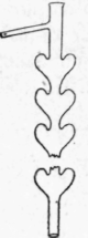
Fig. 43. -The "pear" still-head.
The condensed liquid in any section collects together and falls in drops from the depression in the section below into the funnel; from this it falls on to the top of the middle tube and spreads itself over its surface, falling again in drops from the bottom of this tube and finally flowing through the passage d.
Owing to gradual removal of the less volatile component, the condensing point of a mixed vapour becomes lower and lower as the vapour rises through the still-head ; thus, in any section, the vapour that rises through the inner tube will be hotter than that which reaches the section above. The condensing point of the vapour in the inner tube must, indeed, be higher than the boiling point of the liquid that falls from the little funnel, and when the two components differ considerably in volatility and neither of them is in great excess, evaporation of the liquid on the middle tube may be easily observed. Under such conditions there is a tendency for the drops of liquid from the funnel to assume the spheroidal state, and the progress of a distillation is, indeed, rendered evident by the appearance or disappearance of such drops.
With a pure liquid, the spheroidal drops are never seen unless the quantity of liquid in the still is very small, when, owing to superheating of the vapour, they may be formed in the lowest section.
Modified "Evaporator " Still-head. - A modification of the "evaporator" still-head is shown in Fig. 46. In this, the rather fragile funnel on the three legs is done away with, and the top of the middle tube c is blown into a flattened bulb c', on which the drops of liquid from the depression above fall and collect into a shallow pool which soon overflows, and the liquid then spreads itself as before over the surface of the tube. Spheroidal drops are not nearly so readily formed in this apparatus, but when rapid separation is taking place, the liquid flowing down the sides of the inverted tube breaks up into separate streams.
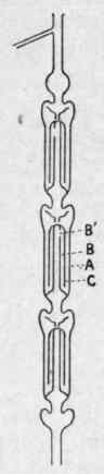
Fig. 44. - The "evaporator " still-head ; original form.
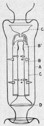
Fig. 45. - One section of the original " evaporator" still-head.
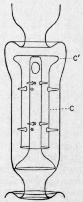
Fig. 46. - One section of the modified " evaporator " still-head.
It will be seen from Table 52 that very good results are obtained with the evaporator still-heads of either form. The sections in the modified apparatus are shorter than in the original one, and for a given height of still-head the efficiency is greater, while, for a given efficiency, the weight of liquid and vapour in the still-head is usually slightly less.
Continue to:
My Books

