Distillation Of Tar. Part 3
Description
This section is from the book "Distillation Principles And Processes", by Sydney Young. Also available from Amazon: Distillation Principles And Processes.
Distillation Of Tar. Part 3
Mason's Still
Mason's still (Ger. Pat. 66097) consists of a raw-tar tank from which the tar is fed into the still, which consists of a series of horizontal and vertical pipes. Each horizontal pipe has a vapour pipe and condenser attached, and as many of these are used as fractions are required.
The tar flows through the zigzag still pipes, which are heated with fire from the bottom one upwards. The lightest fraction comes off the top one, and the heaviest off the bottom, and the last horizontal pipe emits the pitch to the cooler. The difficulty of regulating the firing of such a still must be tremendous and must condemn the plant.
Ray's Still
Ray of Turn (Fr. Pat. 348267) elaborates Mason's still by using a series of retorts in zigzag formation and maintains that good results are obtainable.
Pfropfe's Still
Pfropfe's still (Ger. Pat. 55025, 1890) consists of a series of semi-cylindrical tanks, each separately fired and regulated, and each having its own vapour pipe and condenser. The principle has been more carefully carried out in the Hird Still, which is described later.
Fractional Condensation
Kohn's Still
Walter Kohn, of Lubeck, has invented a most ingenious arrangement which works on the principle of fractional condensation. The tar is pumped under pressure through a series of heating coils from which it is ejected through a nozzle into the still. The nozzle baffles the flow of tar and breaks it up into a fine spray, from which the residual pitch falls to the bottom of the still and thence flows to the pitch cooler, whilst all the volatile vapours pass on into a series of condensers. These are supplied with coils kept at different temperatures, and so the required fractions are obtained. The Lennard still, which is more fully described later, is similar in general outline.
The Wilton Still
The Wilton continuous still, as manufactured by the Chemical Engineering & Wilton's Patent Furnace Company, is shown in Fig. 154, and is there represented with plant for taking off two fractions. The makers maintain that it can be used for distilling down to pitch, and the distillate can be split up into as many fractions as required.
The tar in tank a is pumped up by the pump b, through the pipes c into the heat interchanger or economiser D. In this it takes up heat from the dehydrated tar or pitch according to the use the plant is being put to. It then traverses the pipe cl, and enters the furnace s, which is heated by an ordinary fire of coke or breeze and consists of a series of cast-iron coils superimposed one above the other. It leaves the furnace through the pipes E or El, at a temperature and pressure predeter- mined and varied by the rate and by the temperature of the furnace. It is then allowed to expand suddenly under atmospheric pressure in the vapour box f, whence all the volatile materials pass over through the vapour pipe G, whilst the pitch or dehydrated tar, as the case may be, overflows into the economiser d, and thence to the pitch cooler or storage tank. The vapours from G are cooled by water in the condenser tank h, so that the heaviest of them are condensed and received in I, whilst the more volatile pass over through pipe K into another condenser l, and so on.
The fractions can thus be varied by using as many condensing units as required. The temperature and pressure of working, as already stated, are dependent upon what is required, and must be determined for the individual tar to be distilled ; but those recommended by the makers for dehydrated tar are about 130-140° C. and 30-40 lb. respectively.
It is doubtful whether the plant, as described, is very suitable for distilling tar to pitch, as the fractional condensation of the distillates is likely to give inconsistent results.
Improved Wilton Still
Probably a better plan, which the makers adopt, is to combine this plant with the ordinary pot still.
The drawing in Fig. 155 is self-explanatory after the descriptions already given. The plant can be run almost continuously, as the dehydrating portion is working the whole time and rilling the one pot still while another is being worked off, and the third is cooling before tapping the pitch. If the operations are properly adjusted the third can be tapped and be ready for charging as soon as the first still is full and ready to work.
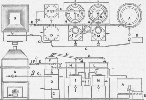
Fig. 154. - The Wilton Still.
A, raw tar tank; B, pump; C, Cl, tar delivery; D, dehydrated tar tank and economiser ; E, Ex, heated tar pipes; F, expansion box; G, G1 vapour pipe and coils; H, first condensing tank; I, first condensate receiver; K, Kl, second vapour pipe and coils; L, second condensing tank ; M, second condensate receiver ; S, dehydrating still furnace.
It is obvious that great economies can be effected by this means, both in saving of fuel and - a most important point - in wear and tear on the pot stills, as they are never subjected to strains set up by sudden cooling through charging cold tar into hot stills.
Lennard's Still
The continuous still of F. Lennard, of Forbes, Abbot & Lennard, Ltd., is worthy of description, as it is based entirely on the principle of fractional condensation and is capable of dealing with large quantities of tar.
The still is shown in Figs. 156 and 157. The heating portion proper consists of a number of cast-iron pipes running to and fro across the width of a brick-work oven, and forming a long coil which is heated by-means of producer gas or oil fuel. One end of the coil is connected to the feed pump p, and the other to the pitch scrubber D. The coil is divided into two sections ; the front one is known as the "front bath " A, and the back one as the economiser B. The only difference in the two is that the economiser coil is directly heated by the flue gas from the still furnace and steam boiler, while the other is protected by brick-work.
The heated tar, passing into the pitch scrubber d, meets in its descent a jet of steam which sets free all the vapours, which pass on through the connecting vapour pipe into the anthracene condenser e. The pitch falls to the bottom of the scrubber and eventually to the cooler and pitch beds. The pipe extending from d to e connects the top of the pitch scrubber with the condensing coils of the specially constructed anthracene condenser. The lower chamber of this condenser, from which the anthracene is collected, is connected with the creosote condenser f, by a pipe through which the vapours pass forward.
The creosote condenser is built similarly to E, and has also a cooler T, the coil of which extends to the receiving tanks. Again the lower chamber of the creosote condenser communicates with the light oil condenser G.
The condensing medium used in e and f is the raw tar which, after exchanging heat in the process, overflows from the top of both condensers into the top of the tar scrubber h. It is there subjected to the action of raw super-heated steam, which drives off all the water and some naphtha, which are condensed in J. The dehydrated tar flows into the hot tar boilers 1 and 2, and is thence pumped by the pumps P (one always kept in reserve) into the still coil a and b.
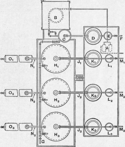
Fig. 155. - Improved Wilton Still.
A, tar pump ; B, dehydrating still furnace ; C, vapour box ; D, naphtha and water condenser; E, naphtha and water receiver ; F, naphtha and water outlet to storage ; G, dehydrated tar pipe; H1, H2, H3, pot stills; J1; J2, J3, pot still vapour pipes; K1 K2, K3, pot still condensers ; L1, L2, L3, pot still receivers ; M1, M2, M3, pot still outlets to storage; N1, N2, N3, pitch tapping pipes ; O1, 02, 03, pitch coolers.
The receiving tanks are provided with an exhaust pipe, connecting to the vacuum pump y, the exhaust gases passing through the vapour absorbers r.
The working of the still is carried out by feeding the tar through the still coils, in which it is heated to the final temperature of about 280° C. It is under pressure when it leaves the coil, and suddenly expands on entering the pitch scrubber. There by aid of live steam all the volatile constituents pass over into the anthracene condenser, while the pitch falls to the bottom. Enough cold raw tar is passed through the anthracene condenser to condense only the anthracene oil fraction, while the remaining vapours pass over into the creosote condenser, and similarly a creosote and a light oil fraction are separated.
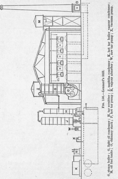
One of the secrets of success of the plant is that good heat interchange is applied, and the tar is dehydrated in the tar scrubber before it falls into the hot tar boilers which are the supply tanks for the pumps to feed the still coil.
Better adjustment and regulation of the fractions have been obtained by slightly varying the above arrangements. The change can be effected by reversing the operations in the anthracene and creosote condensers. That is to say, the vapours are allowed to pass into the top of the column and to cool to the desired degree by letting the cold raw tar circulate in a coil in the condensers.
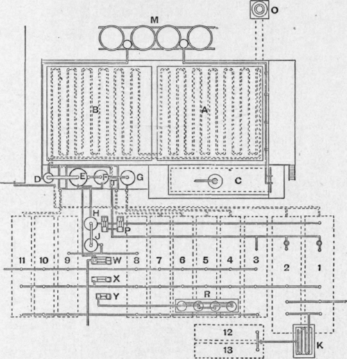
Fig. 157. - Plan of Lennard's Still.
A, front batch of still coil; B. economiser batch of still coil; C, steam boiler; P, pitch scrubber ; E, anthracene oil condenser ; F, creosote oil condenser ; G, light oil condenser ; H, tar scrubber ; J, naphtha condenser; K, hot tar boiler vapour condenser ; M, oil fuel tanks ; O, chimney stack ; P, hot tar pumps ; R., vapour absorber; T, water condenser ; W, raw tar pump ; X, Y, vacuum pumps ; 1, 2. hot tar boilers; 3, spare receiver; 4, 5, light oil receivers ; 6, 7, creosote oil receivers ; 8, 9, naphtha receivers ; 10, 11, anthracene oil receivers ; 12, 13, receivers for vapour off K.
Method of Successive Stills
The Hird Still - The Hird Still is manufactured by W. C. Holmes & Co., Ltd. It is worked on an entirely different principle, and consists of a series of small stills, each one responsible for distilling off one fraction. Here again, as many fractions as desired can be obtained according to the number of units supplied in the plant (see Figs. 158 and 159).
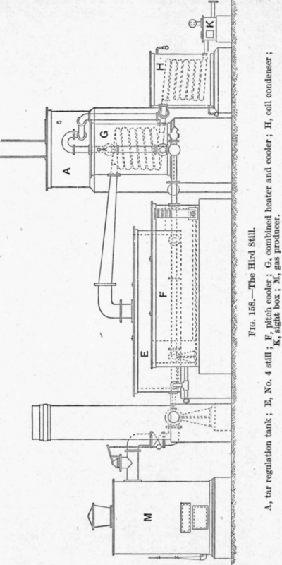
The tar flows from the regulating tank A through all the vapour condensers g, and thus takes up enough heat to drive off most of the water and some naphthas which are condensed in the cooler J. It is further heated by passing through a coil in the pitch cooler f, whence it flows to No. 1 still B. This and the other stills are of the same construetion and consist of cast-iron tanks heated by means of fire tubes running longitudinally and close to the bottom of the still. The firing can be carried out by oil or gas and is done by means of the burners N.
The height of the tar in the stills is only 12-16 inches, and thus relatively small quantities of tar are in the whole plant at any one time. The contents of No. 1 still b are heated sufficiently to drive off only the first fraction, namely the fight oil, when the tar overflows into No. 2 still c, where it is subjected to greater heat and another fraction is distilled off. So the process is continued until the tar has passed through the required number of stills. There are usually four, which give off naphtha, light oil, creosote oil, and anthracene oil, respectively. No. 4 still is not, like the others, provided with burners, but with perforated steam pipes which allow live steam to be blown into the partially distilled tar, this being the usual method of getting off the remaining anthracene oil.
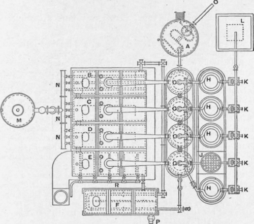
Fig. 159. - Plan of the Hird Still.
A, tar regulation tank; B, No. 1 still; C, No. 2 still; D, No. 3 still; E, No. 4 still; F, pitch cooler ; G, combined heater and cooler ; H, coil condenser ; J, water tube condenser ; K, sight box ; L, oxide purifier ; M, gas producer; N, gas burners; O, tar inlet; P, pitch outlet; R, steam pipes.
The pitch overflows from No. 4 still into the pitch cooler f, and eventually into the pitch beds. The vapours from the stills are partially condensed in the heat interchangers, and finally in the water condensers h; and received in the sight boxes k.
The working of the still is very simple and is very easily and regularly adjusted, so that with little attention regular and constant fractions can be obtained.
In the early types of this plant difficulty arose with the joints between the fire tubes and the sides of the still, as leaks were frequent and corrosion heavy. This difficulty has been surmounted by expanding tubes into steel end plates and bolting the whole on to the flanges of the cast-iron casing, as the more modern plants are supplied with cast-iron instead of wrought-iron stills.
A Comparison between the Intermittent and the Continuous
Distillation Plants
Some of the advantages of the continuous over the intermittent still may be enumerated, viz.: 1. Generally a reduction of fuel consumption.
2. Less loss through bad manipulation of the plant.
A continuous plant when once well started can be fairly easily handled with small chance of anything going wrong. On the other hand a pot still requires a very experienced man to watch it, and even then frothing and "bolting " or boiling over are not infrequent.
3. Wear and tear by corrosion and overheating is not so heavy, as the coils or stills, which have to be subjected to the greatest amount of heat in the distillation, are made of cast iron. Also the overheating of a cast-iron coil does far less damage than that of the bottom of a pot still, especially if it is a little dirty and cleaning out has been neglected.
4. Saving of labour in cleaning out.
On the other hand some of the disadvantages of a continuous still as compared with an intermittent still may be mentioned, viz.: 1. It is claimed that some continuous stills require less labour than periodic plant of equivalent size. This is very doubtful, for a row or battery of pot stills run in proper rotation can be worked with very little labour and expense indeed.
2. The continuity of the continuous still is in many cases a drawback. In works where the tar producer is also the distiller, as in the case of many coke oven works, it is obvious that he can estimate fairly accurately how much tar he will have to deal with, and again, his production will be more or less consistent, so that he can erect his continuous plant to meet his needs, and keep it continually running.
On the other hand the tar distiller who does not produce his own tar cannot estimate the quantity he may expect to obtain from the various gas works, as their make is a seasonal one and is also dependent upon climatic conditions. Unless a continuous plant can be kept more or less consistently running, the charges mount up enormously, and if such a plant has to be frequently started and stopped it is doomed from a financial point of view.
3. Most continuous stills do not produce such a clear-cut fractionation of the products as does the pot still.
Continue to:
My Books

