


Two Handy Clamps
Description
This section is from the book "Handy Man's Workshop And Laboratory", by A. Russell Bond. Also available from Amazon: Handy Man's Workshop And Laboratory.
Two Handy Clamps
The small clamps illustrated in Fig. 58, being of exactly the same size and shape, are a very handy thing to have in the workshop.
To make them, select two pieces of machine steel just large enough to finish to the size of the U frame of the clamp as shown, namely. 2 1/4 by 1 1/2 by 1/2 inches. The two broad faces of each piece must be filed to as nearly a plane surface as it is possible to get them, having each piece 1/2 inch thick. Test the surfaces by placing the pieces together, and carefully mark the two faces which fit the best with a small file cut on one edge of each surface.
The two pieces are now to be sweated or soldered together, having these two marked surfaces next to each other. This is done in the following manner: Heat the pieces until solder will melt upon them, then cover each of the marked surfaces with soldering acid and rub on a coating of solder, Place the two pieces with the solder-covered faces together, and clamp them firmly. Heat again until the solder runs together, then allow them to cool slowly. Upon removing the clam]) you will find that the two blocks of steel are firmly fastened together, making one solid block.
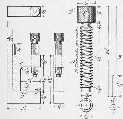
Fig. 58 - Two handy clamps.
Next true up the edges of the block, making all angles right angles. This gives you a neat block of steel 2 1/4 by 1 1/2 by 1 inches. Be sure to make the angle between the sides which will form the back and the bottom of the clamp a right angle, so that holes at exactly right angles may be drilled in a piece of work without removing it from the clamps by first drilling with the clamps in an upright position, and then turning them so that they rest upon their backs, and drilling the second hole.
Now we come to cutting out the inside of the clamps. Lay off the shape of the clamp as shown in Fig. 58, and drill a series of 5/16-inch holes extending from C to D, locating the two end ones as shown in the drawing. Make two hack-saw cuts from the front edge, one to C and one to D. File the surfaces thus formed to the guide lines, making sure that the surface at E is parallel to the bottom.
The next thing is to drill and tap the holes for the screws. These holes are located in the center of each clamp, that is, 1/4 inch from each of the broad faces and 1/4 inch from the front face. These holes must be drilled and tapped for a 5/16-inch screw. Drill the hole in the back of the clamp to hold the pin B. This hole should be 1/8 inch in diameter, and located in the middle of the top face of each clamp, 5/16 inch from the back edge. Drill to a depth of 1 5/8 inches.
Separate the two clamps by heating until the solder holding them together melts.
The bodies of the clamp are completed now, except that they may be polished by rubbing with emery cloth and oil. In polishing, great care should be used not to get the angle between the back and bottom faces out of true.
The screws are turned from a piece of 7/16-inch steel rod. The shape and all dimensions are given in the drawing (./. Fig. 58.) United States standard threads are the best to use, as their edges are less liable to break under strain.
The round top of the screw is knurled, and a 1/8-inch hole drilled through it for the clamping bar to fit into. This clamping bar is made from a 1/8-inch bar. and is 2 1/8 inches long. A hack-saw cut is made in one end to a depth of 1/2 inch. This bar must be rubbed down with emery cloth until it will fit loosely into the hole drilled for it in the back of the clamp. When a sliding fit is obtained, the bottom of the bar must be sprung a little by forcing the sides of the hack-saw cut apart. This will prevent the bar from slipping out of the socket when placed in it.
If a good grade of steel is used, the screws may be hardened by heating evenly to a cherry red and cooling in water.
Continue to:


My Books

