Special Tools And Their Uses. Part 3
Description
This section is from the book "Carpentry for Boys", by J. S. Zerbe. Also available from Amazon: Carpentry for Boys.
Special Tools And Their Uses. Part 3
Steel Frame Breast Drill
These drills are made with both single and double speed, each speed having three varieties of jaws. The single speed is very high, the ratio being 4½ to 1, which makes it desirable to use for small drills, or for use in wood.
A level is firmly set in the frames of these tools to assist the user to maintain a horizontal position in boring. Each of the forms shown has a ball thrust bearing between the pinion and frame. The breast plate may be adjusted to suit and is locked by a set screw. The spindle is kept from turning while changing drills, by means of the latch mounted on the frame, and readily engaging with the pinion. The crank is pierced in three places so that the handle can be set for three different sweeps, depending on the character of the work.
Figure 274 has a three jaw chuck, and has only single speed. Figure 275 has an interlocking jaw, and is provided with double speed gearing. Figure 276 has a universal jaw, and double speed.
Planes
The most serviceable planes are made in iron, and it might be well to show a few of the most important, to bring out the manner employed to make the adjustments of the bits.
In order to familiarize the boy with the different terms used in a plane, examine Figure 277. The parts are designated as follows: 1A is the double plane iron; 1 single plane iron; 2 plane iron cap; 3 cap screw; 4 lever cap; 5 lever cap screw; 6 frog complete; 7 Y adjusting lever; 8 adjusting nut; 9 lateral adjusting lever; 11 plane handle; 12 plane knob; 13 handle bolt and nut; 14 knob bolt and nut; 15 plane handle screw; 16 plane bottom; 44 frog pin; 45 frog clamping screw; 46 frog adjusting screw.
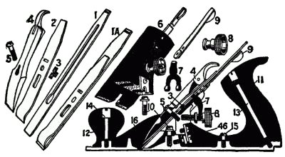 Fig. 277. Details of Metal Plane.
Rabbeting, Matching And Dado Planes
Figure 278 shows a useful form of plane for the reason that it is designed to receive a variety of irons, adapted to cut rabbets.
The detached sections of Fig. 278 show the various parts, as well as the bits which belong to it. 1, 1 represent the single plane irons; 4 the lever cap; 16 the plane bottom, 50 the fence; 51 the fence thumb screw; 61 the short arm; 70 the adjustable depth gage; 71 the depth gage which goes through the screw; and 85 the spurs with screws.
Molding And Beading Plane
A plane of the character shown in Fig. 279 will do an immense variety of work in molding, beading and dado work, and is equally well adapted for rabbeting, for filletsters and for match planing. The regular equipment with this tool comprises fifty-two cutters.
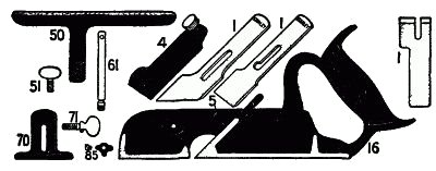 Fig. 278. Rabbet, Matching and Dado Plane.
As shown in Fig. 279, the plane has a main stock (A), which carries the cutter adjustment, a handle, a depth gage, a slitting gage, and a steel bottom forming a bearing for the other end of the cutter, and slides on arms secured to the main stock.
This bottom can be raised or lowered, so that, in addition to allowing the use of cutters of different widths, cutters can be used having one edge higher or lower than the edge supported in the main stock.
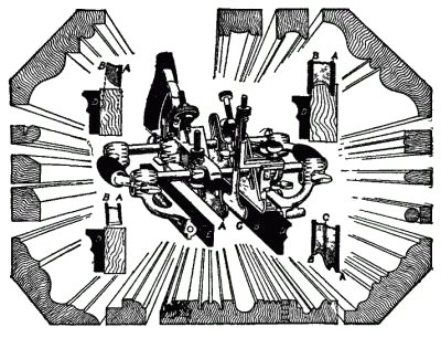 Fig. 279. Molding and Beading Plane.
The auxiliary center bottom (C), which can be adjusted for width or depth, fulfils the requirement of preventing the plane from tilting and gouging the work. The fence D has a lateral adjustment by means of a screw, for extra fine work. The four small cuts in the corners show how the bottoms should be set for different forms of cutters, and the great importance of having the fences adjusted so that the cutters will not run.
The samples of work illustrated show some of the moldings which can be turned out with the plane.
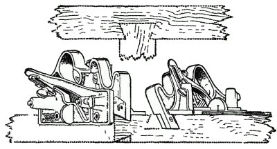 Fig. 280. Dovetail Tongue and Groove Plane.
Continue to:
My Books

