


Plates and Illustrations. Part 7
Description
This section is from the book "Modern Carpentry And Building", by W. A. Sylvester. Also available from Amazon: Modern Carpentry And Building.
Plates and Illustrations. Part 7
Plate 19.
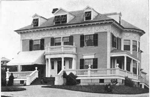
A FINE RESIDENCE. (For floor plans of similar houses see back part of this book.)
Plate 20 represents three different forms of trusses. Fig. 51 represents the form of a truss suitable for a span of thirty or forty feet. Fig. 52 represents the form of a truss suitable for a span of forty or fifty feet. Fig. 53 represents the form of a truss suitable for a span of about seventy feet. These trusses are sometimes made with greater span than is here given.
Plate 21. Fig. 54 represents the form of truss suitable for short bridges, etc.; the bottom timber resting on abutments at A and B. The shaded pieces should be made of well-seasoned hard wood, or cast-iron. This form of truss is also used for supporting roofs of great span, as in halls and churches; the roof being supported from the truss by struts, etc.
Plate 22 represents the framing of a small spire; Fig. 55 being the elevation, and Fig. 56 the plan, of the spire. The rafters are sawed square on the edge at the top. and are fastened to the piece C by wooden pins, giving chance to bore down through C for a vane or finial. This is a much simpler way than to mitre the rafters together at the top. The backing (shown at e) is found as described in Plate 15, Fig. 42.
Plate 20.
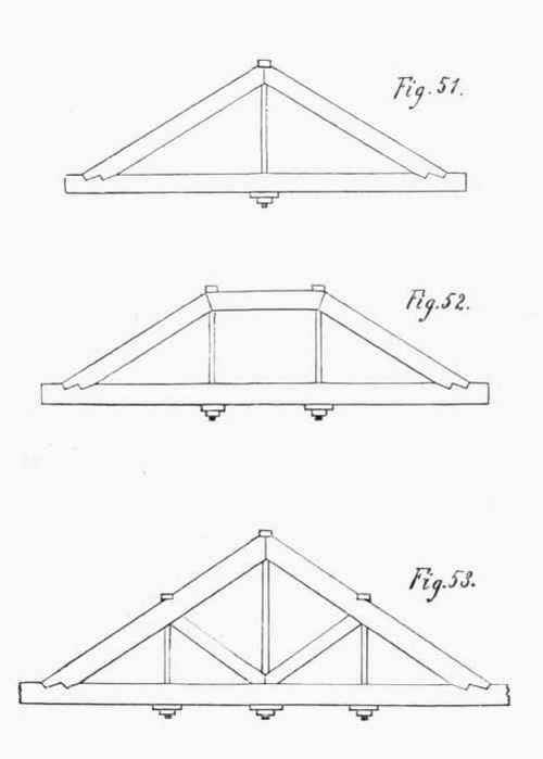
Plate 21.
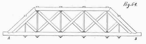
Plate 22.
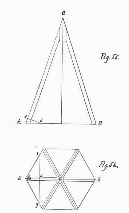
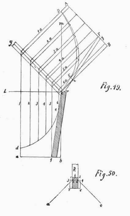
Plate 23 shows the method of finding the forms of the boards for boarding a dome roof horizontally. Fig. 57 is a plan of the boarding of the dome, and Fig. 58 is the elevation of the same. As will be seen in Fig. 58. the principle is the same as finding the envelopes of truncated cones. (See Plate 7, Fig. 21.)
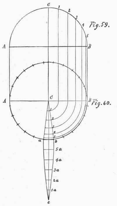
Plate 24 shows the method of finding the form of the boards for boarding a dome roof vertically. Fig. 59 shows the elevation of the dome: and Fig. 60 is the plan of the same, the circumference of which we divide into spaces equal to the width of the boards to be used, a b C (Fig. 60) is the plan of one of these boards. The length of one of these boards is B C, Fig. 59, which we divide into any number of equal parts. Then from a b, Fig. 60, lay off the same number of these spaces to c. Then, from these points of division in Fig. 59, drop lines to the line A B, Fig. 60. Then, with C for a centre, carry these lines across the plan of the board, as seen at 1, 2. 3, 4, 5. Then take the width of the board on the plan at 1, and lay it off at 1 a. Take the width on the plan at 2, and lay it off at 2 a, and so on. Then draw a curved line from c through these points to a, and also from c through these points to b. The result gives the shape of the boards.
Plate 23.
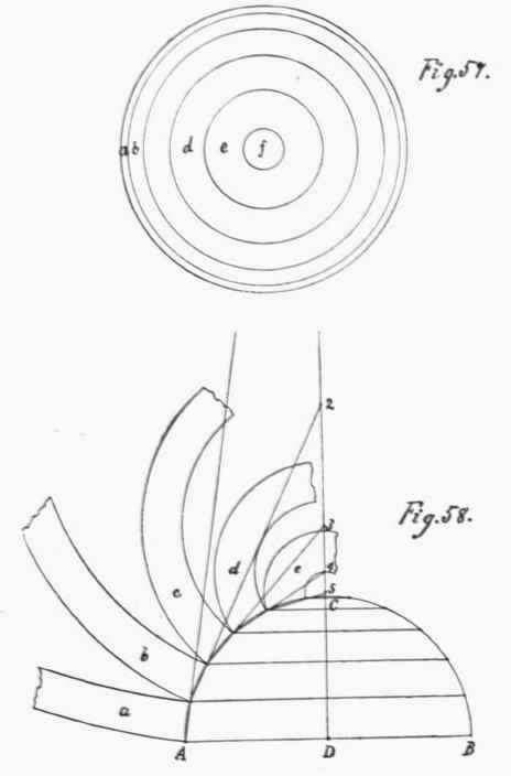
Plate 24.
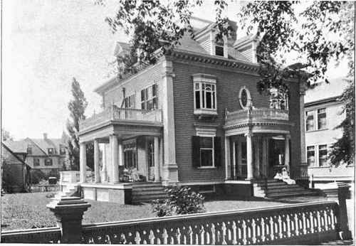
A FINE RESIDENCE. (For floor plans of similar houses see back part of this hook.)
Plate 25 shows the method of finding the rake moulding to fit any gutter; also the method of finding the level moulding to fit the rake. Fig. 61 represents the gutter, Fig. 62 is the rake moulding, and Fig. 63 is the level moulding. To find the shape of the rake moulding: From the gutter to be used, saw off a piece half an inch long; lay this piece on a smooth board, and mark around it, as seen in Fig. 61. Then, from the upper, outer point of the gutter, draw the line a a, giving the pitch of the roof. Then through several prominent points in the outline of the gutter, draw lines parallel to the first line, as b b, c c, etc. Then from the face of the fillet draw the vertical line A B. Then for the rake draw the line A B, Fig. 62, at right angles with the pitch of the roof. Take the distance from a to the line A B, Fig. 61, measured square across, as indicated by the dotted line, and lay it off from the line A B, Fig. 62, parallel with the slant of the roof. Do the same with the other points. Then draw a line through these points, which gives the shape of the rake moulding. Then, to get the shape of the level moulding, take the distance from a to the line A B, Fig. 61, and lay it off square from the line A B, Fig. 63, as indicated by the dotted lines. Do the same with the other points. Then draw a line through these points, which gives the shape of the level moulding.
Plate 25,
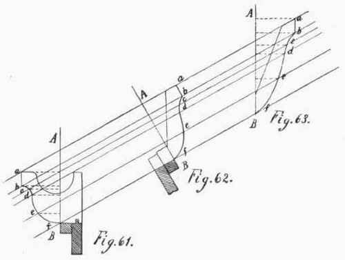
Plate 26 shows mitre boxes for rake mouldings. Fig. 64 shows a box with cuts for mitring the rake moulding to the gutter. The angle across the top of the box is the mitre. (See Plate 36.) The angles on the sides of the box are the same as the down bevel at the top of the rafters. In sawing, keep nearest you the side of the boxes shown in the cut. Place the moulding upside down in the box, keeping the moulded side toward you, as shown in Fig. 65; taking care to have the bevel of the moulding at c fit well against the side of the box. Let a 5, Fig. 64, represent a piece of rake moulding; cut the mitre at a, in the end of the box just above it, letting the moulding lay the same as the line a b. The mitre on the end a will fit the mitre of the gutter on the right-hand side of the gable. Cut the mitre at d, in the end of the box just above d, holding the moulding as before described. The mitre on the end d will fit the mitre of the gutter on the left side of the gable. To mitre the rake mouldings together at the top, the box shown in Fig. 66 is used. The angles on the top of the box are the same as the down bevel at the top of the rafters, the sides being sawed down square. Place the moulding in the box, as shown in Fig. 67, keeping the bevel at c flat on the bottom of the box, and having the moulded side toward you. The moulding a b, Fig. 64, is turned end for end, which brings it the other edge up, a b, Fig. 66; and the mitre for the top is cut on the end b in the end of the box just above it, which completes the moulding for the right-hand side of the gable. The mitre for the top of the moulding for the left side of the gable is cut on the end c of the moulding c d, in the end of the box just above c.
Continue to:


My Books

