Development Of An Anti-Siphon Self-Cleansing Trap
Description
This section is from the book "Improved Plumbing Appliances", by J. Pickering Putnam. Also available from Amazon: Improved Plumbing Appliances.
Development Of An Anti-Siphon Self-Cleansing Trap
To produce an anti-siphon trap, which shall possess all the necessary qualities above pointed out, let us begin with the simplest form of partially anti-siphon trap known at the time of the original passage of the trap-vent law - the common round or pot trap - study the phenomena which are revealed in its operation, and make such modifications in its form as this study shows to be necessary for its improvement. To properly understand the action which goes on, it will be necessary to have all the traps we use made of glass in whole or in part.
Fig. 26 represents such a trap drawn in section, showing the movement of the fluids within it under the influence of a powerful siphonage. Air is forced through the trap by a sudden disturbance of the atmospheric equilibrium on the two sides of the trap. This is equivalent to an increase of pressure on the house side. The air, being lighter than water, passes through the latter, and, in doing so, rapidly drives some of the water out in advance of it. If the siphon-age were continued long enough, all the water above the inlet would be ultimately expelled, for the direction of the air current is constantly towards the outlet, and there is nothing in the form of the trap to reflect the water away from this outlet. The action is always sudden, because the partial vacuum to be supplied in the soil-pipe is produced by a rapid fall of water passing suddenly by the mouth of the pipe to which the trap is attached. It is the suddenness of the action which causes the air to project the water upwards violently in its passage through it, as shown by the arrows. Part of this water strikes the top of the trap, and of this again part is reflected backwards in the form of spray in all directions, and part adheres to the surrounding surfaces in obedience to the law of attraction, and then trickles down the sides of the trap in obedience to the law of gravity and unites with the water below. It is the same as when wind and rain strike a window-pane. The rain adheres to the glass and trickles down while the lighter air escapes.
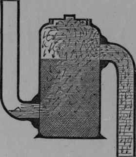
Fig. 26. - First Form. Pot Trap, showing the movement of the fluids within it under siphoning action.
In falling back part of the reflected water again passes across the outlet mouth and is forced out with the general current and lost. Fig. 27 shows an attempt to diminish the fouling surface of a pot-trap, but the result is a more rapid loss of the water-seal under siphonage, as the water is reflected directly into the outlet. Thus the water is by degrees all thrown out, and the total destruction of the seal becomes simply a matter of time dependent upon the proportions of the body of the trap as related to the inlet and outlet arms. How can this time be prolonged, or, in other words, how can the power of resistance to siphonage be increased without increasing the actual size of the body of the trap?
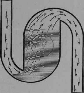
Fig. 27. - Pot Trap, with corners rounded.
Evidently the smaller the amount of water lying in the path of the air current, in proportion to the entire volume of water contained in the trap, the less of it will be removed thereby.
Hence the action of the trap will be very much improved if it be set horizontally as in Fig. 28. The air in passing through the trap now disturbs a much smaller proportion of the water than before, and the loss is consequently less. A very important point gained is that the water is reflected before instead of after passing the outlet mouth, so that the spray is not obliged to pass twice within the influence of its suction. A comparative test on these two arrangements of the same sized trap showed a power of resistance on the part of the horizontal form nearly double that of the vertical. We are now able to greatly diminish the size of the body of the trap, and upon experiment we shall find that the sectional area of the body may be reduced to one-half its original size without reducing the resisting power of the trap below that of the first form.
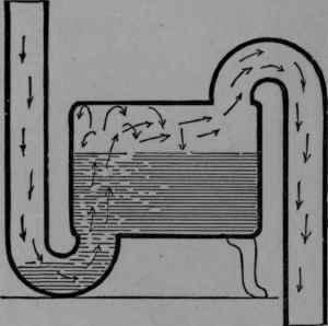
Fig. 28. - Second Form. Pot Trap set horizontally.
Still the trap is not self-cleansing. To render it substantially so, the body must be reduced to very nearly the size, in sectional area, of the inlet and outlet arms. A further reduction of this size, as shown in Fig. 29, without further modification, would, of course, correspondingly reduce its resisting power. To make some modification which will permit of this reduction of size without loss of power is our next problem.
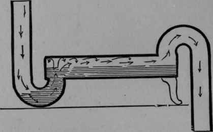
FiG. 29. - Third Form. The diameter of the body is reduced to substantially the same size as that of the inlet and outlet arms.
It is evident that a contraction of the inlet arm at the point of its connection with the body will have precisely the same effect in reducing the destructive action of the air current on the water-seal as would a corresponding enlargement of the body, with this advantage - that such a contraction at two points will not so greatly diminish the force and scouring effect of the water passing through the trap as an enlargement of the entire length of the body. In other words, a contraction at a single point will not diminish the velocity of the water by friction so much as a contraction of the whole length of the inlet arm, which would be equivalent in effect to an enlargement of the body. Practically, it will be found by experiment that a slight contraction at the point named will very greatly increase the power of resistance sought, and that the power lost by reducing the size of the body to substantially that of the inlet and outlet arms may be regained by a comparatively slight restriction of the mouth of the inlet pipe without materially injuring the self-cleansing properties of the trap.
Continue to:
My Books

