Plumbing In The Holland House, New York. Part I - Suction Tank, Filters, Tumps, And Pump Governors
Description
This section is from the book "American Plumbing Practice", by The Engineering Record. Also available from Amazon: Plumbing: A working manual of American plumbing practice.
Plumbing In The Holland House, New York. Part I - Suction Tank, Filters, Tumps, And Pump Governors
(Published In 1891 )
The Holland House is an 11-story marble hotel at Fifth Avenue and Thirtieth Street, New York City.
The architects are G. E. Harding & Gooch, and the plumbers, James Muir, Sons & Co., both of New York. The plumbing-work is extensive and handsome; opportunity having been given to design and execute to the best advantage the complete supply, waste, and vent system, which includes the fixtures and provisions usual in such recent work in this metropolis. Standard details, methods, etc., have been adopted, and although care and skill have been exercised throughout, our description will consider only some features of the design and operation of the general hot and cold-water supply. Other characteristics of the work follow more or less closely the illustrations of methods and details which have appeared from time to time in The Engineering RECORD.
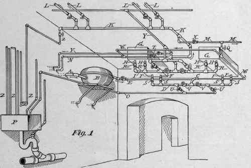
Water is taken from the street mains by a 4-inch pipe A, Fig. 1, and passing through the meter B and pipe E is delivered through branch C to the distribution pipe D, and through its branches at F F F F to the two filters G G. The filtered water then returns through pipes H H, etc., to header I, and thence through a 3-inch branch J to pipe K, which fills the main suction tank through ball cocks on the 1-inch branches L L L L. M is a 1 -inch supply to employees' basement toilet-room, and N is 1½-inch supply direct to the boilers. O is a 1½ -inch waste pipe to empty pipe D into the drip sink P. Each filter has two valves R R, and two valves S S, commanding its four connection pipes H H and F F respectively. These gate valves are connected by links (omitted here to avoid confusion), which are arranged to command them all by a single handle which operates them simultaneously, closing all or opening all at once. Ordinarily, valves Q, T, U, and U are closed and all others are open, but to wash out the filter these valves are opened and V V and X are closed. Unfilterea water is then supplied from pipe E, through by-pass pipe W W and pipe J to the header I, and entering the filters through connections H H H H escapes to header D through connections F F F F, and is discharged through waste pipe O. If it is only desired to wash one filter at once while the other is in use, valves Q T and X are left as usual, and the valves V and U belonging to this filter being respectively closed and opened, the flow of water will be reversed in it and it will be washed as before described, only filtered water will be used. Y Y are separate supplies to the elevator tanks and hot-water boilers, and Z Z Z Z, etc. are drip pipes.
PLUMBING IN THE HOLLAND HOUSE, NEW YORK.
In Fig. 2, A is the open suction tank about 10'x25'x3' deep, supported at the ceiling of the corridor by the 6 inch rolled iron beams B B, etc. It is filled through four ball cocks on branches L L, etc. of 3-inch pipe K (see also Fig. 1), and overflows through the 4-inch pipe C; D is a 3¾-inch telltale, and E is the 6-inch suction pipe to the two Worthington pumps F F for the house service. They deliver through the 5-inch pipe G to the roof tanks, about 140 feet above them, and have a capacity of about 500,000 gallons in 10 hours. H H are hose cocks and I is a pipe to the boiler-room. J J are steam pipes, K K and L L are patent valve regulators, which automatically cut off steam from the pumps when the tanks are full. O is the usual hand throttle valve. P is a ¾-inch telltale from the roof tanks. When they are nearly full water escapes through P and the partly closed valve Q, and producing a pressure in branches J J forces down the piston in the cylinder M, so that its rod R closes the steam valve in S.
Continue to:
My Books

