Plumbing In Amusement Halls And Public Buildings. Plumbing In The Madison Square Garden, New York
Description
This section is from the book "American Plumbing Practice", by The Engineering Record. Also available from Amazon: Plumbing: A working manual of American plumbing practice.
Plumbing In Amusement Halls And Public Buildings. Plumbing In The Madison Square Garden, New York
(Published In 1891.)
The water supply ot the Madison Square Garden is divided into two separate systems. The one for the auditorium building receives water through the 2½-inch pump pipe A, Fig. 1. which delivers to the fire tank S The latter is supported above the roof by the 6-inch iron beams R R R, etc., which are carried by the wal. W and plate-girder T.
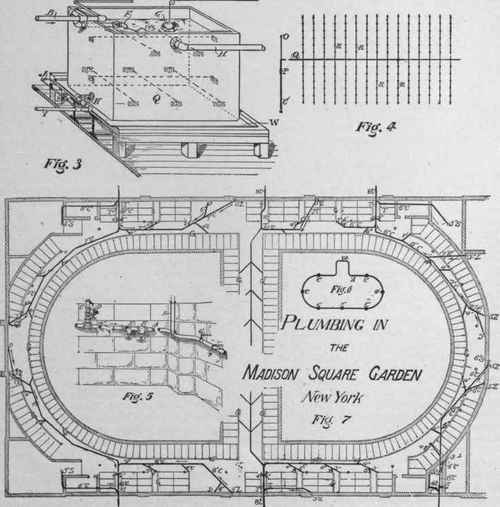
Figure 2 is an elevation at Z Z. Fig. 1. Water enters freely from the pump pipe without any ball valve, and overflows through the 3-inch stand-pipe B to the house tank Q, Fig. 3, which is below it aud conveniently placed some distance away on the upper gallery floor. When this tank is full the pipe is closed by ball cock F, and the water, rising in tank S, rings an electric alarm X. which is in tank S. not shown here. This arrangement insures the constant maintenance of the upper tank S, full of water for fire purposes, as required by law.
The height of the water in house tank Q is always indicated in the pump-room by a gauge operated by the heavy float G. The latter is a copper vessel filled nearly to submersion with sand, and then tightly sealed. The fire tank S must always be full.
The overflow is through 4-inch pipe H to an adjacent slopsink.
I is the 2-inch house supply pipe; J is a ¾-inch branch to an upper washbasin, and also serves as a vent pipe to facilitate the emptying of I when its valve K is closed, and the stop cock L is opened; M is a lead-lined safe.
Figure 4 is a diagram of the system of sprinklers placed in the roof over the stage of the amphitheater for protection, while in use as a theater. C is the 4-inch pipe from the fire tank S, Fig. 2. It is run horizontally for some distance, just under the ceiling of the upper gallery, and then descends by the 2½-inch riser O to the cellar, where it is connected with the fire line A, Fig. 5. P is a check valve, opening with a current towards O; Q is a main supplying the sprinkler branches R R R, etc. Different sections of both Q and R R, etc. vary in size to correspond with the number of sprinklers supplied from given points. All these pipes are suspended directly from the roof trusses.
The sprinkler heads were supplied by John Simmons, New York, for this job. They were placed about 10 feet apart, as indicated by the black circles in Fig. 4, and are nominally closed, but will automatically open whenever the temperature in any part of the auditorium exceeds 160 degrees. They are intended to be operated by the high pressure maintained by the pumps throughout riser O and the rest of the fire line. This pressure closes check valve P, and prevents waste through tank S. Should this pump pressure fail, valve P will open and supply the contents of tank S to the sprinklers or to any hose cock on the fire line.
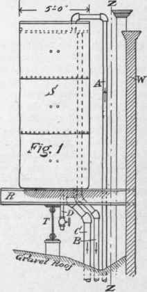
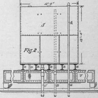
Figure 8 is a general view, and Fig. 9 is a section of the automatic sprinkler head, which is screwed on to the pressure mains R R. etc., Fig. 4. Figure 8 shows the sprinkler head closed, and Fig. 9 shows it open and delivering a spray, as indicated by the arrows. A is the supply tube carrying two slide rods F F, on which the perforated valve cap C moves vertically. Rods F F carry the head L, which has the adjustable yokes M M, to which are pivoted the catches N N.
The stem J of cap C moves freely through head L, and is held up by a weak spring K. Ordinarily cap C is raised to embrace collar P and make a pre«sure contact between ground edge B and copper gasket D resting on the rubber cushion E, which closes the tube A.
Cap C is maintained in position by the catches N N, which secure the lower end of its spindle J, and are bound together by the fusible sleeve O, as in Fig. 8 Tightness of the joint at B is obtained by screwing up yoke M. If now the temperature be raised to 160 degrees the seams of sleeve O will be fused, and it will separate into two parts and release catches N N, as shown in Fig. 9.
The pressure of water in A against cushion E will then overcome the weak spring K, and forcing down cap C and spindle J, open the valve and admit water into chamber H. From this it will escape through the perforations I I, etc.
• The house pump and the steam boiler pump and elevator pumps are all interchaneeably connected, so as to be able to command a 4-inch fire main A, Figs. 5 and 6, which is carried completely around the amphitheater on its outside foundation walls, and is constantly commanded by the special fire pumps at Z. This pipe has several 3-inch risers C C, etc., each of which has a 3-inch hose cock D in a corridor of every floor.
The fire system commands the entire building, and serves the concert hall, restaurant, theater and tower, as well as the amphitheater.
There are also, on opposite sides of the building, two 4-inch hose cocks E, each supplied with hose enough to meet that from the other. Just beyond the cocks E E are gate valves F to shut the water off from the rest of the system if a fire occurs between that point and the pumps.
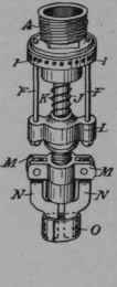
Fig . 8.
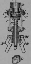
Fig . 9.
The main A is made without elbows, the lengths being very smoothly bent on the ground by hand to a radius of about 3 feet to fit the offsets in the wall, and so as to present a very regular and mechanical appearance. Different kinds of hangers, G, H, I, and J, are used to support the pipe according to circumstances, and are placed at intervals of not more than 10 feet. All of them, except J. are drilled and leaded into the masonry.
Figure 7 is a diagram plan showing the drainage system of the amphitheater and the horse stalls beneath it. The reference letters designate: C, cast-iron drain pipe; D, horse drinking-trough; F, drain from center stalls; G, gutter around the stalls; L, rainwater leader; S, soil pipe; T, main trap; M, branch to street sewer.
The gutter G is simply an asphalt-lined trough, covered with iron gratings, and connects through half-S traps with the drain pipe. Each trap is accessible through a handhole, and every bend of these, and all other drain and soil pipes in the building, are commanded by cleaning caps. As is shown by the current arrows of Fig. 7, almost all parts of the main drain pipes are flushed by the leaders L L. etc. whenever it rains, and by the waste from the horse troughs.
As the horse stalls and basements are unoccupied during intervals of several months each year, the gutter branch traps would lose their seals, and each one would have to be guarded by a gate valve if the stable drain pipes received also the discharge from the soil and waste pipes in the rest of the building. If this large number of valves had been provided, employees would probably neglect to close some or all of them when the stables were empty. It was therefore proposed to make the stable drainage and the general soil and waste systems entirely separate, the former having main traps T T, etc., and the latter main traps T' T', etc., connecting them with the branches M M, etc. to the street sewers. This plan was adopted by the contractors in consultation with John C. Collins, Chief Inspector of Plumbing for the New York Health Department, and the rainwater leader and stable-drainage system is, as above described, entirely independent of the plumbing and drainage elsewhere throughou the house. All the soil and ventilation pipes were subjected to a water-pressure test.
The work was executed by Byrne & Tucker, of New York, who also fitted up the toilet-rooms and all other plumbing in the building, which, although similar to corresponding work done elsewhere by the same firm, does not present unusual features for special description here.
Continue to:
My Books

