Adjustable Control Of Church G S Lights
Description
This section is from the book "American Plumbing Practice", by The Engineering Record. Also available from Amazon: Plumbing: A working manual of American plumbing practice.
Adjustable Control Of Church G S Lights
(Published In 1892.)
In many churches, especially cathedrals and city churches, it is desirable to quickly and definitely vary the intensity of the gaslight in different sections of the building at different periods of the service, This regulation should be done easily and certainly from one place, and should avoid danger of entirely extinguishing the lights, or any lack of uniformity. An arrangement devised to accomplish this has just been applied to the gas system in the Church of the Holy Trinity, Forty-second Street, New York City, and operates as shown in the accompanying illustrations.
The 4-inch gas main A (Fig. 1) terminates on the floor of the auditorium in a corner near the rear, and into it are tapped the 1½-inch branches B B, etc., which each supply all the group of lights in a particular part of the edifice, as the nave, the transept, the chancel, the right gallery, left gallery, etc. Each of these branches is controlled by an ordinary gate valve C, operated by a hand lever D, so that the sexton may from this point graduate any set of lights at will. Figure 2 is a side view of a valve C showing an attachment E intended to fix the opening of the gate at one or more exact positions, thus producing several unvarying intensities of illumination, or to allow it to be entirely closed when necessary. A guide bar F is screwed rigidly to the valve and has one or more rounded seats G, which engage with a spur K. attached to the adjustable bar H, which is fixed at I to any part of the valve lever and slides over bar F. When handle D is depressed from D1 (the full open position), spur K slides easily along down on F until, in the position shown, it rides over into the seat G, which is curved so as to offer some resistance to slipping. The lever is thus held at D as shown, unless the force is noticeably increased to push it down, when K leaves its seat G with a distinct click, and may be pushed successively into other similar seats (not shown here), or the handle D may be completely depressed and the lights shut off altogether. M is a steel spring maintaining spur K in contact with guide F. L is a set screw for adjusting the stops to any position of the valve lever, and N is a set screw for the direct adjustment of the gate stem. This arrangement has been in operation for several months, and is considered convenient and effectual. It was devised and made by Paul S. Bolger, New York, contractor for plumbing and gas work in the church.
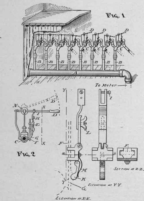
ADJUSTABLE CONTROL OF CHURCH LIGHTS.
Continue to:
My Books

