The Use Of Steel Castings. Part 3
Description
This section is from the "The Construction Of The Modern Locomotive" book, by George Hughes. Also see Amazon: The Construction Of The Modern Locomotive.
The Use Of Steel Castings. Part 3
Tables III. and IV. give the results obtained in a series of experiments on the transverse strengths and torsional resistance of unhammered, annealed steel castings, the specimens being cut from crank webs by the same authority as Tables I. and II.
Table V. gives further results, by different authorities and makers, of the physical properties of steel castings.
Table VI. has been supplied by Mr. James Riley, of the Steel Company of Scotland, and represents the quality of castings turned out by that firm. It is complete and needs no explanation, but the elongations on 8 inches deserve mention.
It may therefore be concluded that steel castings can be supplied very much superior to iron castings or forgings, and to rival those forgings made of hammered or wrought steel. It must be remembered that in a crank axle or any other forging, hammering makes a hard skin which never gets any hotter as the forging cools, consequently internal strains arc set up, and the centre metal is of little use from a physical point of view, and the cruciform shape taken by a pipe in an ingot is well known.
From the foregoing results, it would be reasonable to specify that the castings shall be made in close-grained steel of uniform quality, perfectly sound, free from honeycomb or other defects, and of 28 to 34 tons tenacity per square inch, with a minimum elongation of 15 per cent. on 2 inches; longer bars being difficult to obtain sound when attached to castings. The bending tests to be made upon bars 1¬ inches square, which should be capable of bending cold without fracture over a radius not greater than about one and a half times the thickness of the sample, and through an angle depending upon the ultimate strength; this angle to be not less than 90° at 28 tons, and 60§ at 34 tons per square inch, and in proportion for strengths between those limits. At the present time all locomotive castings are made to the above specification when nothing otherwise has been specified, and all the engine castings for the Admiralty are made to the same limits. The castings to he thoroughly annealed for reasons already stated.
Table I
Test mark | Analysis - per cent. | Section. | Stress. | Fracture | Remarks | ||||||||||
Carbon | Silicon. | Managanese | Length | Diameter. | Original area In sq, Inches | First per, set induced Tons per sq. inch | Breaking stress Tons per sq. inch | Cohesive force. | Contraction of Area. Per cent | Elongation per cent. on 2-inch length | |||||
SA19 | .30 | .22 | .63 | 1.75 | .533 | .223 | 27'0 | 31.0 | 55.1 | 43-8 | 24 | Annealed. | |||
" | " | " | " | " | " | " | 30.4 | 55.1 | 43-8 | 24 | Do. | ||||
" | " | " | " | " | " | " | 19.2 | 33.4 | 56.4 | 41.0 | 24 | Do. | |||
31.6 | 42.8 | 24 | Average. | ||||||||||||
HA 13 | " | " | " | " | " | " | 336 | 46.6 | 26-84 | 16 | Not annealed. | ||||
28.7 = | Percentage advantage. | ||||||||||||||
SA18 | .35 | .23 | .61 | 1.75 | .533 | .223 | 33.0 | 56.0 | 41.0 | 22.2 | Annealed. | ||||
" | " | " | " | " | " | 19-0 | 36.0 | 57.1 | 37.06 | 21.5 | Do. | ||||
" | " | " | " | " | " | " | Spoiled in tooling | Do. | |||||||
34.5 | 39.03 | 21.8 | Average | ||||||||||||
ha 18 | " | " | " | " | " | " | Spoiled in tooling | Not annealed. | |||||||
Percentage advantage. | |||||||||||||||
SA48 | .50 | -41 | .66 | 175 | .533 | .223 | 44.0 | 52.9 | 16.8 | 12 | Annealed | ||||
" | " | " | " | " | " | " | 24 | 45.2 | 48.29 | 6.3 | 5 | Do, | |||
" | " | " | " | " | " | " | 42.2 | 48.06 | 12.3 | 8 | Do. | ||||
43.8 | 11.8 | 8.6 | Average | ||||||||||||
HA 48 | " | " | " | " | " | " | 44.4 | 46.2 | 4.13 | 2 | Not annealed. | ||||
27.1 = | Percentage advantage. | ||||||||||||||
SA60 | .77 | .46 | .67 | 1.76 | .533 | .223 | 39.8 | 40.34 | 1.35 | 10 | Annealed, | ||||
" | " | " | " | " | " | 39.0 | 40.34 | 3.3 | 1.9 | Do. | |||||
" | " | " | " | " | " | 32.4 | 33.6 | 34.21 | 1.8 | 1.5 | Do. | ||||
" | 37.4 | 2.15 | 11 | Average | |||||||||||
HA 60 | " | " | " | " | " | " | 36.4 | 36.61 | 0.8 | Nil | Not annealed. | ||||
10.2 = | Percentage advantage. | ||||||||||||||
SA82 | .98 | .62 | '64 | 1.75 | .533 | .223 | 37.0 | 31-71 | 2-24 | 2 | Annealed | ||||
" | " | " | " | " | " | " | 38.0 | 38.3 | 0.80 | 1 | Do. | ||||
" | " | " | " | " | " | " | 35.6 | 36.2 | 1.80 | 1 | Do. | ||||
" | 34.8 | 1.61 | 1.3 | Average | |||||||||||
HA 82 | " | " | " | " | " | " | 37.0 | 37.3 | 0.8 | Nil | Not annealed. | ||||
Table II
Test marks | Analysis. | Section. | Stress. | Fracture. | Elongation in percentage in a length of - | Remarks. | ||||||||||
Carbon. | Silicon. | Manganese. | Length. | Diameter. | Area. | First per. set. Tons per sq. inch. | Breaking. Tons per sq. inch. | Cohesive force | Reduced area. Inches | Contraction .of area. Per cent. | ||||||
5 in. | 4 in. | 3 in. | ||||||||||||||
028 | .41 | .32 | .47 | 5 | .745 | .4359 | 15.26 | 33.79 | 36.8 | .4003 | 8.16 | 12 | _ | 19 | Not annealed | Taken from the git of a hydraulic riveter casting. |
021 | .26 | - | - | " | .754 | .4464 | - | 32.8 | 48.17 | .2734 | 38.7 | 22 | - | 37 | Annealed | |
024 | .47 | .30 | .64 | " | .741 | .4310 | 15.5 | 32.1 | 33.10 | .418 | 2.9 | 416 | - | 6 | Not annealed | Taken from the git of a hydraulic cylinder Casting. |
025 | .85 | - | - | " | .710 | .3959 | 13.26 | 36.6 | 50.66 | .284 | 28.11 | 14.6 | - | 24 | Annealed | |
151 8 | .35 | - | - | " | .754 | .4464 | 11.7 | 32.3 | 50.27 | .2734 | 38.7 | 15 | - | 28 | Do. | |
027 | .42 | .33 | .49 | " | .768 | .4512 | 19.8 | 24.01 | 24.80 | .4382 | 2.8 | 1 | 1 | - | Not annealed | Taken from the git of a hornblock. |
020 | .42 | - | - | „" | .766 | .4488 | 11.8 | 28.4 | 34.30 | .375 | 15.9 | 18 | - | 16 | Annealed | |
S 25 | .47 | .33 | .47 | " | .724 | .4166 | 13.12 | 30.08 | 40.36 | .3067 | 23.05 | 21.9 | 23.4 | 28 | Do. | Taken from the gits of |
059 | .41 | - | - | „ | .757 | .4500 | 19.54 | 38.19 | 43.05 | .399 | 11.28 | - | 11.5 | 13 | Do | |
060 | .41 | - | - | " | .757 | .4500 | 19.04 | 37.69 | 42.37 | .400 | 11.04 | - | 10 | 12 | Do | |
0157 | .35 | - | - | " | .754 | .4466 | 19.0 | 38.3 | 45.60 | .375 | 16.01 | 14.6 | 14.5 | 16 | Do. | Taken from the gits of horn-blocks & axle-boxes. |
0158 | .35 | - | _ | " | .754 | .4465 | 18.69 | 38.5 | 48.85 | .3462 | 22.46 | 19.25 | 20 | 22.5 | Do. | |
0159 | .35 | - | - | " | .747 | .4382 | 18.64 | 38.4 | 47.59 | .3536 | 19.30 | 17.8 | 18 | 21.5 | Do. | |
06567 | - | - | - | " | .539 | ..2281 | 18.60 | 31.32 | 59-83 | .1194 | 47.65 | - | - | 26.5 | Do. | 4 ft. 4 in. wheel centre. |
06568 | - | - | _ | " | .548 | .2358 | 15.19 | 30.24 | 56.77 | .1256 | 46.78 | - | - | 28.0 | Do. | 2 ft. 6 in. wheel centre. |
06883 | - | - | _ | „ | .540 | .2290 | 17.5 | 35.6 | 39.92 | .2042 | 10.8 | - | - | 14.5 | Do. | Trolley wheel. |
06915 | - | - | - | " | .540 | .2290 | 13.62 | 28.4 | 34.10 | .1907 | 16.7 | - | - | 32.0 | Do. | Piston. |
Table III
Test mark. | Section. | Stress. | Strain. | Remarks. | |||||
Length of the Bar. | Distance between Supports. | Size of Specimen. | B x D2. | Elastic limit. | Maximum Stress in tons per sq. in. | Deflection. | Angle through which the Speci-men passed. | ||
Δ 79 | inches. 14 | inches. 10 | in. sq. 1« | 1.9531 | tons per sq. in. 24.00 | tons per sq. in. 45.25 | 5.73 | deg. 127 | Not broken. |
" 84 | " | " | " | " | 27.77 | 56.53 | 3.55 | 87.5 | Broken. |
" 85 | " | " | " | " | 27.77 | 49.37 | 1.12 | 29.5 | Do. |
" 87 | " | " | " | " | 28.11 | 54.85 | 5.80 | 126 | Not broken. |
" 89 | " | " | " | " | 27.42 | 51.42 | 5.50 | 119.5 | Do. |
" 90 | " | " | •» | " | 27.42 | 51.42 | 5.40 | 119 | Do. |
" 96 | " | " | " | " | 28.11 | 51.43 | 5.84 | 125 | Do. |
" 97 | " | " | " | " | 27.42 | 51.77 | 5.71 | 124 | Do. |
The wheel centres are required by some users to be rough turned, leaving ⅛ inch for finishing where they have to be finished bright. One wheel in fifty to be supplied by the contractor free of cost, selected from the bulk and tested to destruction. From this sample the tensile and bending test will be taken, the results of which will be accepted as the average quality of the whole. It is further required by some users of wheel centres, that each be dropped in a running position, on the end of a spoke, from a height of 2 feet, and allowed to fall upon a rail secured to the top of an ingot of at least 2 tons weight, after which the wheel must be turned round through an angle of 90°, and dropped again in a similar manner. Each casting must be then slung up and hammered with a 7-lb. hammer to ascertain that it is sound. Clauses as to inspection and warranty are inserted to suit the purchaser; the latter is generally for twelve months from the date of commencing work.
Table IV
Test mark. | Length for torsion. | Diameter in inches | Original area in sq. in. | Elastic limit in tons per sq. in. | Maximum stress in tons per sq. in. | Angle through which piece twisted for two diameters long. |
S 741 | 2.256 | 1.128 | 1.0 | 7.617 | 31.015 | Deg. |
274 | ||||||
S 742 | " | " | " | 8.161 | 30.470 | 275 |
S 741 | " | " | " | 9.794 | 32-647 | 2S2 |
S 742 | „ | " | " | 9.794 | 29-926 | 213 |
013 | " | .. | " | 7.6l0 | 30 400 | 278 |
014 | " | " | " | 9.790 | 31.010 | 271 |
015 | " | " | " | 7.610 | 31.550 | 285 |
016 | " | " | " | 8.700 | 32-640 | 316 |
Table V
Test mark. | Authority. | Maker. | Length of Specimen. | Section. | Stress. | Strain. | Fracture. | Remarks. | |||||||
Dimensions. Inches. | Area. Square inches. | Elastic limit. Tons per sq. in. | Breaking weight. Tons per sq. in. | Ultimate sets. Inches. | Per cent. of original length. | Area. Square inches. | Contraction per cent. | Appearance. | Bends. | ||||||
C 337 | Hadfield | Hadfield's Steel Foundry Co. | 2 | .7979 | •5 | - | 32.5 | - | 29.0 | - | 40.4 | deg. | |||
C 2¬ B | " | " | " | - | 32.5 | - | 27.9 | - | 33.4 | ||||||
C 147 | " | " | " | - | 34.5 | - | 27.7 | - | 352 | ||||||
C 2¬ A | " | " | " | - | 32.0 | - | 26.8 | - | 30.9 | ||||||
C 111 | " | " | " | - | 40.0 | - | 19.0 | - | 20.0 | ||||||
C 117 | " | " | " | - | 45.0 | - | 15.0 | - | 18.0 | ||||||
C 1 | " | " | " | - | 52.0 | - | 4.0 | - | 6.3 | ||||||
C2 | " | " | " | - | 56.8 | - | 4.0 | - | 5.5 | ||||||
C3 | " | " | " | - | 64.0 | - | 6.0 | - | 8.0 | ||||||
" | - | - | - | 26.0 | - | 36.5 | - | 40.4 | 1st centre arm | Loco, wheel centres. | |||||
" | - | - | - | 26.0 | - | 37.6 | - | 50.0 | " " rim | ||||||
" | - | - | - | 27.0 | - | 28.5 | - | 33.6 | " " bal. weight | ||||||
" | - | - | - | 26.5 | - | 20.6 | - | 223 | 2nd „ arm | ||||||
3223 | " | .540 | .229 | - | 31.1 | •60 | 30.0 | .1190 | 48.0 | " | |||||
3224 | " | .500 | .196 | - | 32.6 | •55 | 27.5 | .1070 | 45.4 | " | |||||
3435 | " | .560 | .246 | - | 32.5 | •27 | 13.5 | .2200 | 10.5 | Granular & fibrous | |||||
3436 | " | .565 | .250 | - | 31.2 | •34 | 17.0 | .2000 | 20.0 | " 30% " | |||||
3437 | " | .565 | .250 | - | 31.6 | •60 | 30.0 | .1350 | 46.0 | Fibrous | |||||
3438 | Snowdon | John Rogerson & Co., Wol-singham, Darlington. | 2 | - | .237 | 18.6 | 32.4 | •64 | 32.0 | .1194 | 49.6 | 100% fibrous | 180 | Not broken. | Size ⅝" and [¾" radius |
3439 | " | - | .216 | 18.5 | 32.9 | •60 | 30.0 | .1244 | 42.3 | " " " | " | Do. | |||
3441 | " | - | .223 | 18.8 | 32.2 | •62 | 31.0 | .1152 | 48.3 | " " " | " | Do. | |||
3442 | " | - | .227 | 17.3 | 31.7 | •65 | 32.5 | .1134 | 50.0 | " " " | " | Do. | |||
3443 | " | - | .227 | 19.8 | 37.0 | •45 | 22.5 | .1661 | 26.8 | 20% fib., 80% gran. | " | Do. | |||
3444 | " | - | .225 | 18.3 | 31.6 | •62 | 31.0 | .1225 | 45.5 | Fibrous " " | " | Do. | |||
3445 | " | - | .214 | 17.7 | 32.2 | •60 | 30.0 | .1134 | 46.9 | " .... | " | Do. | |||
3472 | " | - | .223 | 20.1 | 35.2 | •50 | 25.0 | .1520 | 31.8 | 4% fib., 96% gran. | 115 | Broken. Size | ⅝" and 7/16" [radius | ||
3473 | " | - | .220 | 16.5 | 30.4 | •65 | 32.5 | .1134 | 48.0 | 100% fibrous | 180 | Not broken. | |||
3474 | " | - | .212 | 19.6 | 32.4 | •60 | 30.0 | .1134 | 46.5 | " " | 85 | Broken. | |||
3475 | " | - | .220 | 17.8 | 32.3 | •65 | 32.5 | .1194 | 45.7 | " " | 180 | Not broken. | |||
3476 | " | - | .220 | 18.5 | 34.6 | •52 | 26.0 | .1520 | 30.9 | 10% fib., 90% gran. | 100 | Broken. | |||
3477 | " | - | .224 | 18.4 | 32.0 | •60 | 30.0 | .1452 | 35.1 | 100% fibrous | 180 | Not broken. | |||
3478 | " | - | .233 | 18.5 | 35.0 | •42 | 21.0 | .1960 | 15.8 | 100% granular .. | 180 | Do. | |||
3479 | " | - | .220 | 18.6 | 31 4 | •60 | 30.0 | .1194 | 45.7 | 100% fibrous | 180 | Do. |
Table VI
Test mark. | Length of Specimen. | Section. | Stress | Strain. | Fracture | Bends without Fracture | Remarks. | Passed by inspector. | |||||
Diameter. | Area. Square inches. | Elastic limit. Tons per square inch. | Ultimate lead. Tons per square inch. | Extension. inches. | Per cent. | Area Square inches. | Contraction pet cent. | Appearance | |||||
in. | deg. | ||||||||||||
Y 272 | 2 | .76 | .463 | 20.5 | 34.9 | .65 | 32.5 | 237 | 47.6 | Silky | 180 | Engine coatings | Admiralty |
Y 282 | " | .75 | .441 | 20.6 | 34.7 | .65 | 32.5 | .212 | 51.9 | " | 180 | " | " |
Z 683 | " | .77 | .465 | 19.7 | 35.2 | .60 | 30.0 | .220 | 52.7 | " | 180 | " | " |
Z 689 | " | .77 | .465 | 19.3 | 33.3 | .65 | 32.5 | .246 | 47.5 | " | 180 | " | " |
Z 696 | " | .78 | .477 | 19.4 | 32.7 | .70 | 35.0 | .220 | 53.8 | " | 180 | " | " |
Z 703 | " | .75 | .441 | 19.9 | 35.3 | .75 | 37.5 | .196 | 55.5 | " | 180 | " | " |
Z 716 | " | .80 | .502 | 19.1 | 31.4 | .75 | 37.5 | .255 | 49..2 | " | 180 | " | " |
Z 719 | " | .79 | .490 | 18.1 | 31.8 | .70 | 35.0 | .229 | 53.2 | " | 180 | " | " |
Z 739 | " | .76 | .453 | 17.0 | 29.3 | .70 | 35.0 | .237 | 47.6 | " | 180 | " | " |
No. 1 | 1.13 | 1.002 | 19.8 | 33.8 | .75 | 37.5 | .502 | 49.8 | " | 180 | " | Russian Government | |
" 7 | " | .89 | .622 | 18.0 | 30.4 | .75 | 37.5 | .301 | 51.6 | " | 110 | " | " " |
.. 13 | " | .88 | .608 | 18.9 | 32.5 | .70 | 35.0 | .311 | 48.8 | " | 99 | " | " " |
" 15 | " | 1.11 | .967 | 18.6 | 32.4 | .72 | 36.0 | .477 | 50.6 | " | 99 | " | " " |
" 10 | " | .99 | .769 | 18.3 | 32.5 | .75 | 37.5 | .390 | 50.7 | " | 100 | Locomotive wheel | Railway |
,. 11 | " | .99 | .769 | 18.3 | 31.4 | .70 | 35.0 | .385 | 50.0 | " | 100 | centres | " |
" 12 | " | 1.00 | .785 | 17.9 | 31.5 | .70 | 35.0 | .410 | 52.2 | " | 100 | " | " |
" 330 | 8 | .88 | .608 | 17.0 | 29.4 | 2 .20 | 27.5 | .311 | 48.8 | " | 90 | Ship castings | Lloyds |
„ 353 | " | .85 | .567 | 17 4 | 29.2 | 2.00 | 25.0 | .284 | 50.0 | " | 94 | " | " |
" 373 | " | .85 | .567 | 18.4 | 30.3 | 1.84 | 23.0 | .295 | 52.0 | " | 127 | " | " |
" 374 | " | .84 | .554 | 18.1 | 29.9 | 2.40 | 30.0 | .290 | 52.5 | " | 127 | " | " |
As far as the analysis is concerned, probably it is best left in the hands of the steel maker, because so much depends upon the process. Sometimes a good analysis gives worse physical results than an interior one, owing to the working of the charge during the earlier or latter stages of the heat; however, castings having an analysis of C '18 to .28, Si .20 to .40, S .02 to .07, P .03 to .07, Mn .3 to . 75, would give similar results to those tabulated in Table V. under the second authority, providing that the heat had been worked to the best advantage. Finally, in a great number of observations made by the author for Mr. Aspinall, it was observed throughout, that the highest carbon with simultaneous high silicon gave the worst castings, and the best results were when the carbon was .28 per cent., or below, or when the content of carbon was from 10 to 26 per cent, less than that of silicon. Perhaps this does not quite coincide with a comparison of Tables I. and II., but it must be remembered that these tables are given for specific reasons. The first, to show the effect of annealing and also chemical composition, and therefore various percentages of elements may be expected; whereas Table II. shows chiefly the remarkable reduction of the content of combined carbon by annealing. The reliability of these tables is unimpeachable, they satisfy a specific purpose, but the author's personal experience of the physical and analytical results of some hundreds of castings, is summed up by low carbon in conjunction with high silicon or vice versa, these conditions being imperative, .26 per cent, carbon being the highest preferable amount for mild castings. High silicon with low carbon will work admirably in the forge, with as much as 1.5 per cent, of the former, providing the latter is very low, say about 15 per cent.


Fig. 89.

Fig. 90.

Fig. 92.

Fig. 93.

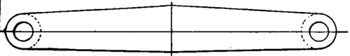
Fig. 100.

Fig. 101.
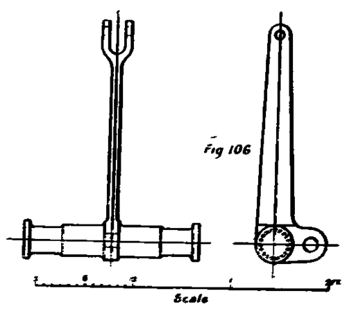
In Fig. 87 is seen one-half of the motion plate, from the centre line of the engine to the right frame, with its forked attachment for securing one end of the anchor link of Joy's motion, whilst an end view is shown in Fig. 88. Two views of the cross-head are given in Figs. 89 and 90, to which may be cast sufficient metal to be drawn down in the forge to the required dimensions of the piston rod. The driving wheel centre is given in Fig. 91, the leading and trailing being identical, with the exception of the balance weights, which are of course very much lighter; Fig. 92 being a half section through the crank pin boss. Figs. 93 and 94 are sections of the arms at the top and bottom. Reference has already been made to the designs of wheel centres, as well as the horn-block, which is shown in Fig. 98, with its keep, Fig. 99. This horn-block is of a useful design, but is frequently modified to suit the various types of locomotives built by different engineers. The Joy reversing shaft is shown in plan and elevation in Figs. 95, 96, and a cross-section, Fig. 97. Figs. 100 and 101 give two views of the brake hanger, which is swung from the frame at one end, coupled up to the brake cylinder by means of suitable connecting rods from the other, and having the cast-iron brake block attached in the centre, Figs. 105 and 106 being the tender brake shaft, The firebox foundation ring is given in cross-section in Fig. 102 and in isometric in Fig. 102a. The cross stay between the frames in front of the fire-box is shown in Fig. 103, and the safety-valve seating in Fig. 104. Similar designs to Fig. 104 are adopted for the mud collector in the barrel, just in front of the fire-box, and also where cast-steel domes are used they require a similar seating. Fig. 107 is the tender spring link, and the draw bar spring box is shown in section in Fig. 108.

Fig. 102A.

Fig. 104.

Fig. 105.

Fig. 108.
Continue to:
My Books

