Duplication Of Samples
Description
This section is from the book "Human Vitality And Efficiency Under Prolonged Restricted Diet", by Francis G.BENEDICT, Walter R. Miles, Paul Roth, And H. Monmouth Smith. Also available from Amazon: Human Vitality and Efficiency Under Prolonged Restricted Diet.
Duplication Of Samples
With nearly all types of respiration apparatus, even those connected with chambers, the kind of experiment ordinarily employed is such that a repetition is usually easily made and with relatively slight expense, particularly with animals. On the other hand, when one proposes working with a large group of human individuals, to duplicate an experimental session is an expensive procedure; hence it was necessary at the outset to provide for duplicate analyses and duplicate samples. For this reason, two sampling cans were provided. The second can (C2, fig. 8) is connected with an exact duplicate of the absorbing system in series with the can C1. This second absorbing system has a separate Crowell blower (shown in the upper part of fig. 11 as F2), its duplicate large Williams bottles for absorbing water vapor, and its train of purifiers consisting of soda-lime bottle and small Williams bottle (see figs. 11 and 12). Thus both samples are taken at identically the same time.
In figure 8 but one soda-lime and one small Williams bottle are shown. As a matter of fact, looking down on top of the table (figure 12) one sees four sets of absorbers. At the bottom of figure 12 is shown the set connected with blower F1 and at the top the set connected with blower F2. As each sampling can and blower is provided with a double set of soda-lime and Williams bottles, we have two series for blower F1 withdrawing air from can C1 and two series connected with blower F2 withdrawing air from can C2. With this arrangement we can, by means of valves V1 and V2 (fig. 12) and their corresponding valves V3 and V4, deflect both air-currents from one series of purifiers to the other at the end of any 20 or 30-minute period and thus begin another experimental period without intermission.
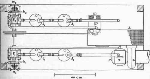
Fig. 11. - Top view of lower shelf of absorption apparatus of group respiration chamber.
The parts are lettered the same as in fig. 8. h1 and h2 globe valves for by-passing air-currents from blowers, F1 and F2. m1 and m2, rubber tubes for fine regulation of amounts of air delivered by blowers. These tubes are opened and dosed by telegraph sounders actuated by contacts d1 and d2 in fig. 13.
This method of treatment assumes at the start that the same amount of air will be discharged through both 10-mm. openings in the bottoms of cans C1 and C2. Since the discharge from the rotary air-impeller, a, is somewhat nearer to the opening of the bottom of the can C\ than it is to the opening in C2, one might think that there would possibly be more or less of a short-circuiting effect between the discharge of a and the opening B, and inequality in discharge to C1 and C2. This difficulty is avoided by a series of wire screens (W, fig. 9) which breaks up practically all air-currents. Tests have shown that the discharge through the two 10-mm. openings is exactly the same.
To measure the amount of air delivered through these openings is a difficult problem. No anemometer thus far devised can record the discharge of air through these holes with a sufficient degree of accuracy for comparison purposes, but the air discharged must be measured for checking; this problem is intimately connected with the problem of collecting and analyzing a sample of the discharged air, for our fundamental assumption is that the large proportion of the air will be discharged into the room free, but a small sample must be collected for analysis. To assume that there will be constancy in the discharge of the air through these various holes presumes that the resistance against which the air is discharged should be the same in all cases, that is, there must be atmospheric pressure outside the openings. To discharge a definite volume of air against atmospheric pressure and simultaneously collect it presents a new problem.
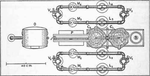
Fig. 12. - View from above of top of absorption table of group respiration chamber.
B, circular opening for delivery of air to outside; C1 and C2, cylindrical cans on top of wind chest; L1, M1 and L2, M2, duplicate sets of soda-lime and sulphuric-acid containers for absorbing carbon dioxide of air coming from C1; L3, M3 and L4, M4, duplicate sets of soda-lime and sulphuric-acid containers for absorbing carbon dioxide of air coming from C2, V1 and V2, 3-way valves to deflect air from L1, M1 to L2, M2; V3 and V4 3-way valves to deflect air from L2, M3 to L4, M4, P, petroleum manometer for indicating pressure in either C1 or C2; 0, meter for measuring amount of air passed through the system.
Continue to:
My Books

