Collection Of Air Sample
Description
This section is from the book "Human Vitality And Efficiency Under Prolonged Restricted Diet", by Francis G.BENEDICT, Walter R. Miles, Paul Roth, And H. Monmouth Smith. Also available from Amazon: Human Vitality and Efficiency Under Prolonged Restricted Diet.
Collection Of Air Sample
The collection of the sample of air from the aliquoting device delivered against atmospheric pressure is not unlike an earlier experience in the development of the respiration calorimeter at Wesleyan University. In this apparatus the Blakeslee pump was made to deliver the air of 49 strokes into the room and of the fiftieth stroke into a pan covered with a rubber diaphragm and delicately counterpoised. From this covered pan air was continuously withdrawn through a series of U-tubes at such a rate that by the time the next sample was ready to be delivered into the pan the first sample had been practically all withdrawn.1 By this method, however, air was but intermittently discharged into the pan and with a pump that, while not capable of exerting any great positive pressure, nevertheless could easily overcome the slight friction of the counterpoise weight of the rubber diaphragm. Our present problem, however, was to remove the air from the sampling can as rapidly as it was introduced, the air as supplied from the wind chest being under only slight positive pressure, amounting to but a few millimeters of water. It thus became necessary to adjust the receiving chamber so that the pressure of air inside was always atmospheric.
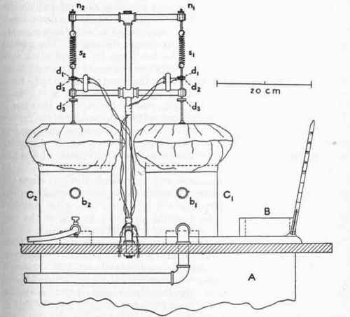
Fig. 13. - Details of device for regulating pressure inside of cylindrical cans above wind chest.
A, wind chest; B, opening for delivery of major portion of air to outside; C1, C2, cylindrical cans above wind chest; b1, b2, openings for delivery of air from C1, C2 to outside; the weights of .the bathing caps on tops of cans C1, C2 are counterpoised by the springs, s1, s2, the tensions of which are regulated by the nuts, n1, n2; when the pressure inside of cans C1, C2 gets too low, the contact shown between disks d\, d2 is closed, and the current passing through this circuit draws down the telegraph sounder shown in fig. 11; this permits the opening of tube m1 or m2 (fig. 11) and by-passes a portion of the air, thus drawing less air from the can C1 or C2. In this way the amount of air drawn from C1 or C2 is regulated so that the air inside of either can is practically always at atmospheric pressure, d3 is a disk for preventing the bathing cap from rising unduly.
1 Atwater and Benedict, U. S. Dept. Agr., Office Expt. Sta. Bul. 109, 1902, p. 27.
To do this the receiving chambers or sampling cans into which the small orifices opened were made as follows: A copper can was used, which was provided with a cover consisting of a lady's bathing cap, made of pure gum, securely fastened around the edges. The greater part of the weight of this rubber top was borne by a light aluminum disk placed inside the cap. To the disk was fastened an upright brass rod with tight closure about the rod. At the top of this brass rod a hook was attached to a slight spiral spring suspended from a standard. The combined weight of the rod, disk, and rubber cap was thus borne by the spring. Without this suspension effect the weight of the rubber would increase the pressure. With the suspension effect the bag was held in position so that at any one moment there would be complete atmospheric pressure if provision were made to remove the air as soon as it was delivered into the can.
The details of these diaphragms and their suspension and electrical connections are given in figure 13, which shows their normal position when the ventilating air-circuit is not in action, i. e., when counterpoised by means of the delicate spiral springs, s1 and s2, at the top. The tension on the springs can be easily adjusted by the nuts n1 and n2 and thread on the ends of the suspension hooks. The air coming from the wind chest is thus discharged into a chamber, which, though provided with a flexible top, is nevertheless absolutely air-tight. Since it is necessary in many preliminary adjustments of the apparatus to have a free opening from each of the cans into the air, aside from that leading to the blower, a small piece of brass tubing is soldered into the side of each can at b1 and b2. When the apparatus is running, the two pipes are easily closed by inserting solid rubber stoppers.
If the air is removed from this chamber more rapidly than it is delivered, there will be diminished pressure inside the rubber diaphragm, thus pulling down on the spring from which it is suspended. The ultimate result will be a slightly decreased pressure above the opening leading into the wind chest. If, on the contrary, the air is withdrawn more slowly than it is delivered, the rubber diaphragm over the can will distend, raise the aluminum disk, lessen the work of the spring, and produce a slight positive pressure at the orifice into the wind chest. Thus, while air will be delivered free into the room from the large opening, it will be compressed in the rubber diaphragm over the sampling can. It is therefore necessary to remove the air from the sampling can at the same rate that it is delivered in order that atmospheric pressure may be maintained.
Continue to:
My Books

