


"Sea Scout" Racing Yacht Model. Part 3
Description
This section is from the book "Things To Make In Your Home Workshop", by Arthur Wakeling. Also available from Amazon: Things to Make in Your Home Workshop.
"Sea Scout" Racing Yacht Model. Part 3
A round or oval shaped hatch opening for bailing out any water and for airing the inside should be cut in the deck (Fig. 53). A 1/8 in. thick doubling or reinforcing piece should be fitted under the deck around the opening as shown above. A simple hatch cover may be made of two pieces of wood glued together; or better, a piece of mahogany or walnut for the top and a piece of cork to fit snugly in the opening. The underside of the deck should be painted with two coats to prevent its warping when wet.
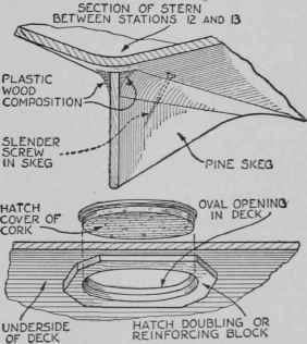
Fig. 53. - How wooden skeg is fitted, and construction of hatch opening and cover.
The deck is fastened to the hull with glue and fine brass screws or brads. The brads should be placed close to the outside edge so as to be covered by the rail and slanted in so as not to come through the outside of the hull, especially fore and aft where the hull slopes in. It should be noted here that unless the oval hatch in the deck is of the size indicated on the plans (sufficiently large to permit access of a hand for tightening the keel bolts nuts inside the hull), it will be necessary to attach the lead keel before the deck is fastened down.
The model next requires the 1/8 in. thick mahogany or walnut rail, breast-hook, and stern trim, which are fastened in place with fine brads and glue. However, do not fasten the rail where the chain plates (Fig. 55) are to go, because the chain plates must be slipped under it.

Fig. 54. - Diagram giving location of the four deck beams and the extra vertical support under the mast.
As the next step, the entire hull should be smoothed with fine sandpaper and the surface put in as perfect condition as possible.
It is necessary to make a split wood pattern of the lead keel - a pattern split vertically in half the long way. Two short pegs are set in one half of the split pattern to fit in corresponding holes in the other half; these pins should extend about ¼ in. and fit loosely in the holes. The pattern should be slightly larger than the finished keel to allow for trimming, fairing to the hull, and smoothing.
For the molding, two molder's flasks and molder's sand of proper consistency and dampness are desirable, although homemade flasks and plaster of Paris (instead of molder's sand) may be used, the latter making very smooth castings.
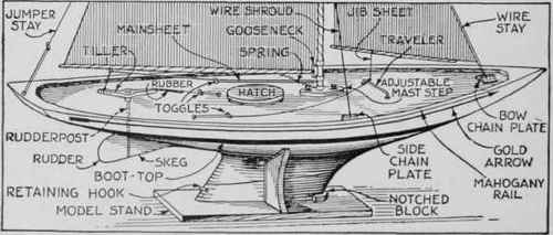
Fig. 55. - The Completed hull of the 42 in. Sea Scout model showing all the deck fittings and the stand.
Detailed information on pattern making and molding may be found in any-public library. It is advisable to obtain such information or to visit a foundry; however, Fig. 56 shows the molding in detail. About 8 lbs. of pure lead are required, also an iron kettle and a ladle for pouring. Lead becomes molten at a relatively moderate temperature, so that the heat from an ordinary gas burner is sufficient.
The cast-lead keel should be smoothed and accurately fitted to the wood hull with ¼- or 3/16-in. holding bolts. These may be cast into the lead or tapped into it afterwards; or holes may be drilled all the way through the keel and the boltheads countersunk in the lead. The keel should be trimmed away as necessary to obtain the correct trim and weight, so that the model will float on the designed load water line. Use a generous amount of white lead in the bolt holes and between the lead keel and the deadwood to insure a water-tight job.
A hand plane or any cutting tool may be used on pure lead without injury to the tool. A coarse cabinet rasp also is useful for trimming the lead. When the keel is secured to the hull and finally shaped and faired to the deadwood, it should be sanded smooth. The finished keel should weigh about 5.3 lbs.

Fig. 56. - How the mold for the lead keel is prepared. Use either sand or plaster of Paris.
For the rudderpost (Fig. 57) a 7/32-in. brass tube is fitted through the hull. Care should be taken to drill close to, and in line with, the after side of the rudder skeg. Threading the outside of the rudderpost tube at the lower end and turning it into a hole in the wood slightly smaller than the tube insures a tighter job. It is advisable to use white lead in this hole also.

Fig. 57. - Mast step, rudder, two types of goosenecks, toggles, traveler, chain plates.
The model should be carefully cleaned and sanded with No. 00 sandpaper preparatory to applying the paint and finish. The model may be painted, enameled, varnished, or lacquered in a variety of suitable colors. For a paint or enamel job, a thin priming coat of white lead and oil is applied. Care must be taken not to paint out the load water line - the glue line between lifts C and D. A narrow stripe - "boot-topping" or "boot-top" for short - of contrasting color is usually painted between the topside paint and the bottom paint. A strip of adhesive tape, cut to the boot-top's measurements, may be applied to the hull while painting above and below.
Continue to:


My Books

