


"Sea Scout" Racing Yacht Model. Part 2
Description
This section is from the book "Things To Make In Your Home Workshop", by Arthur Wakeling. Also available from Amazon: Things to Make in Your Home Workshop.
"Sea Scout" Racing Yacht Model. Part 2
The simplest way to prepare these is to en-large the half size half-breadths plan given on Popular science Monthly Blueprint No. 106, listed in the Appendix. There are two blueprints la the Sea Scout set, Nos. 106 and 107.

Fig. 50. - Body plan showing the shape or cross section of the hull at the station points 1 to 15 and at the stern.
Begin with lift A, as the interior sawed out may be used for a smaller lift. Fit ¼-in. wooden dowels at both ends to fix the relative position of each layer and prevent any slipping or inaccuracy in gluing up. The station or section lines on each layer must coincide. It is advisable to mark the midship station (No. 8) distinctly on each lift and to make these marks coincide. Care should be taken not to have the dowel holes too deep or they may come through when the outside corners are pared away in the final shaping of the hull.
Before gluing make a careful trial clamping with wood hand screws. If plenty of hand screws are available, lifts A, B, C, D, E, F, and G are glued together at one time. If the number of hand screws is limited, one lift may be glued on at a time. When no hand screws are available, the necessary pressure may be obtained by using weights or by fitting strong backs and bolts for tightening. Care should be taken not to apply too much pressure, which might crack a lift.
A waterproof casein glue, mixed according to the manufacturer's directions, should be used. Casein glue, which comes as a white powder, is mixed with cold water to a consistency of thick cream. It should be stirred continuously for twenty minutes before being used. Mix only enough to finish the job in hand, as it soon hardens and is then unfit for further use.
When the lifts are glued up and the glue has hardened for at least twelve hours, secure the model to the bench top by clamping it with hand screws at lift A or by fitting wooden cleats or dogs to the bench top. With a chisel, gouge, plane, and cabinet rasp, cut off the square corners just to the lift edges and sandpaper the whole smooth. This should give the correct shape to the hull.
It is sometimes advisable to make cardboard templates from sections or stations 4, 6, 8, 10, and 12 on the body plan for testing the model form, as indicated in Fig. 51. Leave the forward half of the lift A with square edges to allow lift X to be clamped on a little later. Leave the bottom lift G with square edges but gouge out part of the interior.

Fig. 51. - How cardboard templates may be used, if necessary, to aid in shaping the hull accurately.
Clamping the model in the vise by means of the square edges on lift G is not as secure as it might be because of the rounded form, so first gouge out the interior at the bottom in lift F only sufficient to allow the keel bolts to be inserted. When this is clone, cut out to the profile the "deadwood" portion of the keel and glue it on, holding it by means of the ¼-in. (or 3/16-in.) keel bolts instead of clamps. This deadwood piece now is a firm member for securing the model in the vise for gouging out the remainder of the interior, as shown in Fig. 52. The lower part of the keel block, if made of two pieces temporarily screwed together, will later serve for making the keel pattern.
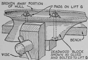
Fig. 52. - A partial view of the rough hull showing it held in the vise by the deadwood.
In gouging out the interior, care must be taken to work with the grain of the wood and to test often so as not to cut through the hull. Holding the hull over a strong light will show if the wood is dangerously thin. The shell or wall of the hull should be about 1/8 in. thick. Note, however, the pads which are left at the bottom for receiving the nuts of the keel bolts. A plastic wood composition is useful in repairing any defects in the hull, and it acts as a binder when applied over seams on the inside of the hull wherever there appears to be any defect in the gluing.
The next step is to glue lift X on the forward half. To save material, this may be in two pieces mitered on the center line forward. Then finish shaping the outside and gouging the inside.
To draw on the sheer line, lay out points with a pair of dividers on each station the distance of the sheer line from the water line (the glue line) between lifts A and B. Bend a thin strip of wood or a spline through these points and draw in the sheer line. Cut this line with a spokeshave or a small plane and test by eye to see that the curve is a fair one, without humps or hollows.
A wooden skeg (Fig. 53) just forward of the rudder should be fitted for the best racing results. Younger or less skillful boys sometimes find it difficult to make a good job of this skeg, and it may be omitted if desired. If it is fitted, this should be done next. It is fastened to the hull with glue and long, thin brass screws from the inside, as shown below. The skeg is "streamlined" and given additional stiffness by a heavy plastic wood fillet. The weight of the hull should now be about 1.6 lbs.
Four 3/16 by 1 in. pine deck beams cut to the proper camber curve are next secured in place by means of brads and glue. They are located as shown in Fig. 54. A support 1/8 by ¾ in. is fitted from the deck beam to the shell bottom under the mast to take the pressure of the mast at that point.
The interior of the hull should be painted with two coats of white lead paint before fitting the deck. The deck is made of one piece of 1/8-in. clear white pine or mahogany. It is advisable to cut out the deck to the shape of the hull first, leaving it about 1/8 in. oversize all around for trimming alter it has been fastened down. If the deck is to be plank-marked, the necessary lines should be drawn on it with a hard pencil before it is put in place.
Continue to:


My Books

