


Making An Electric Bell. Part 3
Description
This section is from the book "American Library Edition Of Workshop Receipts", by Ernest Spon. Also available from Amazon: American Library Edition Of Workshop Receipts.
Making An Electric Bell. Part 3
Fig. 51.

(9) Method" of producing continuous ringing from an ordinary Electric Bell. - The method works well, is inexpensive, and any one with ordinary intelligence could make and fix one for himself. Of course, the bell must have a contact breaker. In Fig. 52, a is the bell; b, hammer, in the centre of which is screwed or soldered a piece of metal projecting outwards 1/2 in. The head of hammer is flat, circular, with a hole in centre; c, piece of brass hung loosely on the screw, to which wire is attached, leading to bell as shown; d, screw and wire attached, leading to battery. On the bell being rung, the oblong piece of brass c is liberated, falling on to d, making a new circuit, producing continuous ringing until c is lifted up. (J. W. Fisher.)
(10) Connecting Telephones And Bells
In Fig. 53, d is a piece of brass shaped like the shafts of a cart (only the telephone takes the place of the horse), secured to the base - board by a short piece of steel spring. The telephone, by its weight, brings b into contact with c, thereby breaking communication with the speaking instrument, and bringing the bell e into readiness for receiving a signal. Directly the telephone is removed, d springs up, making contact at b a, so bringing the telephone into connection with the line wire /. As shown in the sketch, the bell is ready to receive a signal from the distant station, but by pressing down the spring g (similar to the key used for the Morse telegraph), you cut off connection at h, and bring your own battery into action, thereby ringing the bells. The board should be suspended against a wall.
Fig. 52.

Fig. 53.

(11) Another Plan
Make connections like Fig. 54 at both ends: a, switch; b, telephone; c, bell; d, battery; e, earth (water or gas - pipe will do); f, line - wire. The switch is made of a piece of wood with 3 studs at bottom, connected with the wires as shown. A strip of brass is made to slide over them so as to make contact, and communicate with line wire. When not in use, the handle must be in contact with the centre stud at both ends, to call attention at the other station. Put the switch to No. 3 stud, which will ring his bell for a few seconds, and put your switch back to stud 2. The other station now must just do the same to let you know that he is there, and as soon as the bell stops ringing, move the switch to stud 1 to connect telephones. The other station must move his switch as soon as he has rung reply to your call. You can now go on with your speaking, and as soon as finished move switch to stud 2 at both ends.
Fig. 54.

(12) Another Plan
The push in Fig. 55 is of rather peculiar construction. A spring a is connected, through a binding - screw 6, with the line - wire c, and is fixed so that the free end plays between two contact - pieces d and e, the former of which is connected with the telephone /, the latter with one pole of the Leclanche cell g. The other pole of the battery is connected to the return wire, or, in the case of there being no return wire, to earth. The normal position of spring is as shown in section, pressing against d. The telephone / is thus in circuit. By pressing the stud, the spring is brought into contact with e, and the bell h at further station rings.
Fig. 55.

(13) Another Plan
The following method of connecting bells and telephones with one wire has the advantage that the telephones are thrown out of the circuit while the bells are ringing, and thus not subjected to the battery current, wherefore perhaps it is to be preferred. In Fig. 56, a b are 2 switch arrangements, having a movable arm fixed to the top button, capable of sliding over the lower 3, and making contact with either, c and d are the batteries, e and f the telephones, and g and A the bells. In the diagram, the switches are shown in the position in which they are always left after using. Then, by turning either of them on to the end button, both bells ring, thus letting the ringers know that the circuit is complete. The switch is then moved back for the answer. When that has been received, both switches are moved to the middle button, which brings the telephones into circuit, and conversation may be carried on. It is necessary to remember to move the switches back after the conversation is finished. This arrangement is used over 300 yd. of uninsulated copper wire, which is carried over the roofs of several houses and across 3 streets without any insulation whatever, and the gas - pipe is used for the return circuit.
It employs 3 Leclanche cells of 1 pint capacity; 2 were not powerful enough. This has been in use for several weeks, and the weather does not seem to have had any bad effect on bells or telephones. A wrinkle connected with the telephone is, that the strength of the magnet makes more difference than some might sup - pose. A pair which were working miserably, when taken to pieces, and the magnets re - magnetized, work splendidly. Iron cores don't make any perceptible difference for ordinary purposes, and 2/3 oz. of wire works perhaps rather better than 1/4 oz., but there is very little difference.
Fig. 56.
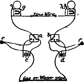
(14) In Brailsford's arrangement, Fig. 57,1 magnet suffices to ring the bell and to indicate the place from which the signal has been sent. The electro - magnet is fixed to a block capable of sliding up and down in a vertical tubular case. When the block is at the top of the case, it is held up by a catch; the catch has an arm extending from it, which carries a soft iron armature just in front of the poles of the magnet, in order that when the armature is attracted it shall release the catch and allow the block to drop to the bottom of the case. As the block so descends, the poles of the magnet are carried past a series of other soft iron armatures, situated at distances apart one below the other. If a current is passed through the coils of the magnet when it is opposite to any of these armatures, traded, and mores a distance towards the magnet, and in doing so shifts a signal or indicator a connected to it, and armature has been moved. When the block reaches the bottom of the case, the poles of the mag - net come opposite another armature, by means of which the belt is to be rung, and an electric current being then caused to pass through the coils of the magnet, the bell is rung, and (in the event of a continuous signal being desired) does not cease to ring until the block is lifted up again to the top of the case.
Continue to:


My Books

