


Making An Electric Bell. Part 2
Description
This section is from the book "American Library Edition Of Workshop Receipts", by Ernest Spon. Also available from Amazon: American Library Edition Of Workshop Receipts.
Making An Electric Bell. Part 2
The wires are connected to the push B, and battery C. Thus, when the push B is pressed down, the circuit is closed, the iron core in electro - magnet is magnetised, and pulls the iron armature on b close up, thus causing the knob to strike the bell, and at the same time breaking the circuit by leaving the platinum tip on c. The push B consists of a thin brass spring d and a binding - screw e, with a brass plate connected to it going immediately under the wooden knob f. The cell C is a Leclanche, with the carbon rod g in porous jar, well packed with an equal quantity of coke and lamp - black, oxide of manganese, and the zinc cylinder A. The lines show how the wires are to be.
Fig 44.


(3) Connecting Bells And Telephones By One Wire
Use a relay, as shown in Fig. 48 at a. The switch b has 3 knobs,Nos. 1, 2, 3 The handles of both switches most be turned on No. 1 when not in use, awaiting calls, both on No. 2 for telephonic messages, and either on No. 3 for ringing bell to call attention at the Other end. It would be better to have the bell single stroke (the connec - tions make the difference), and the relay will make it continuous. Make the relay of small size, and to fit in at the back of the switch. The action of the relay is thus: - When handle is turned on No. 3 right - hand switch, a current of electricity is sent through wire to the other end, through No. 1 knob to electro - magnet in relay, which draws down the spring until it touches the other wire, which sends a current through the battery, and strikes the bell. The other connections will explain themselves.

(4) Single - Stroke Bell
Fig. 47 explains its construction. Instead of having a contact - breaker fixed at a, the circuit only goes through the magnet, thus only ringing when the button is pressed, b and c are connected with the battery.
Fig. 47.
(5) It is possible to ring 2 bells with only 1 wire by having 2 series of cells: but this involves much more expense and trouble than laying a double wire and one series of cells. You can work with 1 wire if you allow both bells to ring at the same time, and have a battery at each end, or you can so arrange the batteries and bells as to throw battery of one end in circuit with the bell of the other end. and so on, as in Fig. 48, where a represents the gas - pipe; 6, line wire joined up with bells in circuit; c and d, 2 wires going through cells and on to pushes in connection with line wire. Thus, when either of the pushes is closed down, the battery and distant bell are in circuit, and vice versa.
Fig. 48.

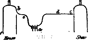
(6) The subjoined arrangement (Fig. 49) is a simple way of effecting the same object as the preceding. Let a b be bells at shop and house respectively; connect the line wire c with a binding - screw of each bell, as shown. Have a battery at shop and another at house, d and e; connect line - wire also with one pole of each battery; connect the remaining binding - screw of each bell with a metallic plate; connect the remaining poles of batteries, each with a metallic plate. Instead of the ordinary " push," arrange metallic springs at shop and house, permanently connected with gas - pipe f, and so placed that when at rest they are in contact with the plates.
Fig. 49.

(7) Fig. 50 shows another solution of the same difficulty. The battery a is placed in the house. At b and c are 2 small levers, which can be moved so as to put the line wire d, and the short wire e, which constitute the poles of the battery, in connection with the earth in 2 sets of ways. The figure shows the connection in case it is wished to ring the house bell from the shop. Before leaving the house, bring the lever 6 in connection with the wire which traverses the electro - magnet of the house bell; thus e is brought into connection with the earth at /. Whenever, then, in the shop, you press down the lever c, you complete the circuit, and the house bell rings. Before leaving the shop, raise the lever o so as to bring the shop bell into the circuit, and when returning to the house you can complete the circuit, and cause the shop bell to ring every time you press down the lever b.
Fig. 50.
(8) Continuous - Ringing Bell
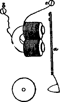
This is more complicated than the single - stroke, as will be seen by Fig. 51. A small piece of brass or iron is fixed in a suitable way (riveting is best) on to the armature of the bell upon which rests edgeways a piece of flat brass a, shaped as in the diagram; it is supported by a piece of brass tube, through which a screw b passes, securing it to the board - not too tightly, however, so as not to allow of its swinging easily; a piece of brass rod or stout wire c is driven into the base - board in such a way that when a is drawn down by the spring e, a good contact is formed between a and c. A wire is taken from e to one binding - screw of the bell, and a wire is taken from the brass tube which supports a to another separate binding - screw d. The dotted lines represent wires as well as the other lines; the dotted lines also represent the direction of the current for the continuous action, using the same wire to the zinc element. The current passes from the zinc to the contact - screw, through the coils to c, across a, down b, and out through the binding - screw d to the carbon element.
The bell is stopped by pulling a cord attached to a, which breaks the contact, and which, if pulled hard enough, forces the armature towards the magnet by rubbing against the piece in the armature (which must be made in the shape of the diagram). When it gets above the piece in the armature, the armature springs back, and a rests on the piece of brass again, ready for another time.
Continue to:


My Books

