


Horology. Part 8
Description
This section is from the book "The Engineer's And Mechanic's Encyclopaedia", by Luke Hebert. Also available from Amazon: Engineer's And Mechanic's Encyclopaedia.
Horology. Part 8
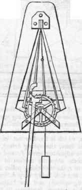
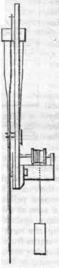
The detached escapement was applied first to chronometers or time-pieces, but is now also used for astronomical clocks; and various excellent constructions have been invented by different artists, amongst which we may mention those of Hardy and Reid. In 1812, Mr. Prior, jun. was rewarded by the Society of Arts for the construction of a detached remontoire escapement for clocks, which possesses considerable merit. The advantages of this escapement consist in the freedom of its parts from friction; in the exact and equal impulse which it will continue to give to the pendulum, unaffected by the clogging of oil and increased friction of the train; and in the small power required for restoring the tension of the remontoire spring, which does not require to be wound up quick, or to be pushed beyond any catch or spring to keep it in its proper situation. The engravings on page 696, with the following description extracted from the Transactions of the Society, will explain the construction. The swing-wheel, Figs. 1 and 3, has thirty teeth cut in its periphery, and is constantly urged forwards by the maintaining power which is supplied by the small weight; two spring detents are used to catch the teeth of the wheel alternately; these are, at the proper intervals, unlocked by the parts marked 1 and 3 upon the pendulum rod, intercepting two small pins projecting from the detents, as it vibrates towards the one or the other; the renovating or remontoire spring is fixed to the same stud as the detents; it is wound up by the highest tooth of the wheel, as seen in Fig. 1, (its position when unwound being shown by the dotted lines.) This being the case, suppose a tooth of the wheel is caught by one of the detents, this prevents the wheel from moving any further, and keeps the renovating spring from escaping off the point of the tooth; in this position, the pendulum is quite detached from the wheel; now, if the pendulum be caused to vibrate to the right, the part of it marked 2 comes against the upper pin, seen in Fig. 2, projecting from the renovating spring, and pushes this spring from the point of the wheel's tooth; on vibrating a little further, the pendulum removes the detent which detained the wheel, by the part 3 striking the lower pin, Fig. 2, which projects from the detent; the maintaining power of the clock causes the wheel, thus unlocked, to advance until detained by a tooth resting upon the end of the other detent on the opposite side; by this means the renovating spring will be clear of the tooth of the wheel as it returns with the pendulum, and gives it an impulse with its pin pressing against the part 2 of the pendulum, until the spring comes to the position shown by the dotted line, in which position it is unwound, and rests against a pin fixed against a cross bar of the plate; the pendulum continues vibrating to the left, nearly to the extent of its vibration, when the part 1 meets the pin in the same detent, and removes it from the wheel, and unlocks it; the maintaining power now carries it forward, pushing the renovating spring before it until another tooth is caught by the first detent, which detains the wheel in the position first described, the renovating spring being wound up ready to give another impulse to the pendulum.
The pin is not fixed to the renovating spring itself, but is part of a piece of brass, which is screwed fast to the renovating spring, and is made very slender near the screw which fastens it; this permits the renovating spring to give way, if, by the weight being taken off the clock, or any other accident, the escape wheel should be wound backwards, so as to catch on the detents improperly. The weight in the preceding figures merely represents the means by which the escape wheel was put in motion in the model presented to the Society, which consisted merely of the escapement; but when attached to a clock, the remon-toire spring is wound up by the maintaining power of the clock transmitted to the escape wheel by means of the train.


Chronometers and clocks for astronomical purposes, in which extraordinary nicety in the exact measurement of time is necessary, have, besides the compensation pendulums or balances, and detached escapements, before described jewelled pallets, and all their pivot-holes jewelled: they are likewise provided with a contrivance for continuing their motion during the time of winding up, when the action of the maintaining power is suspended. For this purpose a second larger ratchet wheel is added on the same arbor which admits the clock to be wound up, but with teeth pointing the contrary way; a strong sprint, usually the greatest portion of a circle, connects this large ratchet wheel with the great wheel of the clock, which is on the same axis with it, one end of this spring being attached to the great wheel and the other to the large ratchet; and a catch proceeds from the inner face of this back plate to the teeth of this ratchet, which prevents its moving back when the clock is winding up, and serves as a support for the reaction of the maintaining spring.
When the clock is left to the action of the weight, the small ratchet turns round the larger one, and contracts or coils up the spring till it has strength sufficient to impel the great wheel and train; and when the action of the weight is suspended, as in winding up, the spring, freed from the contracting power of the weight, expands itself and forces round the great wheel, its action in the contrary direction on the great ratchet being prevented by the catch before mentioned. Leroy is considered to be the inventor of the spring impeller to prevent loss of time in winding up, but the idea of continuing the motion of the train during this time originated with Huygens, for he contrived a method by which the weight of his clock should continue to act on his train whilst it was drawing up; the weight in his clock having been made to draw up in a similar manner to that used in common wooden clocks, instead of being wound up as in our metallic clocks.
Continue to:


My Books

