


Horology. Part 4
Description
This section is from the book "The Engineer's And Mechanic's Encyclopaedia", by Luke Hebert. Also available from Amazon: Engineer's And Mechanic's Encyclopaedia.
Horology. Part 4
When the art of clock-making had attained a high degree of perfection, and the application of this instrument to astronomical observations rendered the utmost accuracy desirable, it was soon perceived that the varying length of the pendulum rod, in consequence of its expansion by heat and contraction by cold, was a source of irregularity, which it was deemed difficult to overcome. To diminish as much as possible these variations, we are indebted to that eminent artist, George Graham, for the first application of the principle, which, under various modifications, has since been applied to preserve unchanged the centre of oscillation in a pendulum, and thus to insure the performance of all its vibrations in the same length of time. Those substances which were found to be least alterable by changes of temperature, such for example as wood, and particularly deal (pine), were employed in the best clocks. As the different metals are affected by heat in different degrees, Graham conceived the idea that the greater expansion of one might be employed to counteract the less expansion in another.
After a series of trials, during a period of five or six years, he succeeded perfectly, by attaching to the pendulum rod a vessel containing mercury, which liquid, when the rod was expanded by heat, rose, from the same cause, in the vessel which contained it, so as to compensate for the downward expansion of the rod. This improvement was completed in the year 1721. Five years afterwards John Harrison, a carpenter in Barton, in Lincolnshire, subsequently so celebrated f*6r his improvements in chronometers, invented and applied to a clock of his own manufacture the pendulum, which from its form is called the gridiron pendulum. In this the expansion of the iron rod is corrected by the greater expansion of rods of brass or of zinc, which tend, to raise the bob in the same degree in which the expansion of the main rod tends to lower it, and it of course is retained in the same place: in this form the compensation pendulum is, to the present day, most commonly made. The principle upon which these pendulums were constructed has received various modifications in the hands of different artists; Harrison's rods, for example, instead of being arranged in the form of a gridiron, have been inclosed in a tube, and greater elegance and compactness, with a more easy mode of adjustment, have been attained; these, however, we believe, comprise the whole merit of the modern improvements.
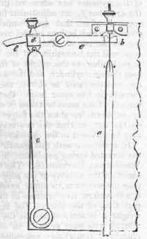
The annexed figure represents the mode of compensation proposed by Dr. Fearn. a is the pendulum rod suspended by a flexible spring, in the usual manner, from the cock b; c is a rod or bar of zinc attached to the back plate of the clock, by a screw at its lower end. The head d of this bar works upon a pin, which forms a joint, as represented in the drawing. Through this head there is a mortice, which allows one end of the lever e e to pass through it, and within which it may be fixed firmly by means of a tightening screw. K The lever ee is attached to the clock-plate by a screw, which is also its fulcrum. Through a slit in the inner end of this lever the suspending spring passes, and is closely embraced by it on its lower side. The operation of this apparatus will readily be conceived; as the rod a lengthens by heat, or contracts by cold, the rod c will be similarly affected. The' expansion of c will cause the inner end of the lever to descend, and, consequently, to embrace the suspending spring at a lower point, and thus to diminish the effective length of the pendulum.
The mode of adjustment is obvious, as a greater or lesser motion may be given to the lever, the upper end of the rod c being made to approach or recede from its fulcrum.
To obtain the requisite accuracy, an adjusting screw may be ma de to act upon the head d.
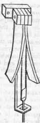
In the year 1818 a reward was given to Mr. Reid for a compensation pendulum, in which the bob rested in a hollow cylinder of zinc, through which the rounded end b c of the steel pendulum rod is passed, the zinc itself being supported by the nut e at the end of the rod. As, therefore, the rod lengthened by heat, carrying the bob downward, so the upward expansion of the zinc raised the bob; and if the relative lengths of the steel and zinc were so proportioned that the amount of their expansions was equal, it is evident that the compensation above described would be perfect; but it is extremely difficult to effect this accurate proportioning of the lengths of the two metals. The length of the zinc at first must be such that its rate of expansion shall be in excess, and it must be cautiously reduced by repeated trials till the requisite accuracy is attained; this, however, is not done, except at a considerable expense of time and attention, to avoid which Mr. Reid has introduced the following modification.
He forms a hollow screw in the cross bar f of the bob g, and an external screw on the same rake on the end of the zinc cylinder d; this latter is purposely made too long for due compensation, but its effective length may be commodiously and accu-rately reduced to what is required by screwing it up as represented in the figure; but after this has been done, supposing the nut e to have remained stationary, it is evident that the extent of gravity of the pendulum itself will have been lowered by the bob descending exactly as much as the upper end of the cylinder has advanced through the hole in the cross-barf; an adjustment for time is therefore required after that for compensation has been effected, which is done in the usual way, by screwing up the nut e. This latter compensation, however, will not be required, if the rakes of the screws f and c are proportionate to each other, as the weight of the bob alone is the sum of the weights of the bob, the zinc cylinder, and the nut. Thus, if the former weight be assumed as ten, and the latter as eleven, the screw at f must have ten threads, in the same length that the screw at c has eleven threads.
Continue to:


My Books

