


Fire Engine. Part 3
Description
This section is from the book "The Engineer's And Mechanic's Encyclopaedia", by Luke Hebert. Also available from Amazon: Engineer's And Mechanic's Encyclopaedia.
Fire Engine. Part 3
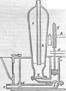
Fig. 3 is another section, taken vertically through the hinder part of the engine, showing one of the cylinders o and the air vessel s.
On the floor of the cistern is placed the standing-piece, or sole, of cast-brass, which reaches from the nozle x through the suction cock y, and afterwards divides itself into two branches, so as to open under each of the barrels; one of these passages is seen in the figure, the other is situated exactly behind it; through these channels water is conveyed to the pumps, either from the cistern itself, or from any place without, by means of the suction pipes. The two cylinders are screwed down upon the standing, or as it is frequently termed, the sucking piece, with plates of leather between them, which makes the joints water-tight, and also forms the valves, one of which appears at t. Each cylinder has a projecting piece cast on its lower side, which forms a seat for the air vessel, ana a communication into it, which is closed by a valve opening upward at v. The leather valves are kept closed, and also strengthened by a piece of metal having a tail, which passes through the leather, and is cross-pinned under it.
When the engine is at rest, all four of the valves continue closed by their own weight; but when the engine is working, two are opened and shut alternately, q is the sector on the shaft k, and g is one of the treddles in its bearing on the piston-rod; s shows the internal construction of the air vessel. The action of this engine is exceedingly simple; on raising the piston r a partial vacuum is produced in the cylinder o, when the pressure of the atmosphere forces the water up the suction pipe through the cock y, along the sole, and lifting the valve t into the cylinder. Upon the piston reaching the top of its stroke, and beginning to descend, the valve t closes, and prevents the water, which has entered the cylinder, from returning by the way it came; being urged by the forcible descent of the piston, it is driven along the communication into the air vessel, raising the valve v in its progress, which closes again the moment the water has all passed through. While this process has been going on, the other cylinder has become filled with water, which is now discharged in its turn into the air vessel, and so on continuously.
On the water first entering the air vessel, a quantity of air is expelled; but so soon as the water rises to the dotted line, the lower orifice of the exit pipe becomes covered, and the escape of any farther portion of air is prevented; the air is therefore gradually driven by the continued influx of water into a much smaller space than it originally occupied, and by its elastic force reacting on the surface of the water, drives up the upright pipe z, along the leather hose, and out at the branch-pipe, with so great velocity as to break windows, etc, and throw up a jet to the height of sixty or seventy feet. New-sham met with great encouragement, his patent being renewed for a second term; his engines were eagerly purchased by the government, nobility, and gentry, the different parishes, and by the various fire insurance companies thai were formed about this time; viz. the Hand-in-Hand, in 1696; the Union, in 1714; and the London Assurance Corporation, in 1720.
Fig. 2.
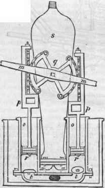
Fig. 3.
In the year 1792, Mr. Charles Simpkin took out a patent for an improvement in fire-engines, which consisted in the employment of separate chambers for containing the valves, instead of placing them within the cylinders and air vessels, as was done previously. Mr. Simpkin, (afterwards of the firm of Hadley, Simpkin, and Lott,) Long Acre, London, materially altered the internal arrangement of the working parts, and constructed an engine much more compact and convenient than any of its predecessors. As a travelling engine it was infinitely superior to any previously built; the only method of conveying Newsham's engine about, was by placing it in a cart or waggon made purposely for it, and many of our metropolitan readers will recollect that the london Assurance, Royal Exchange, and Phoenix Fire Offices, continued to run Newsham's engines in this manner to the end of the year 1832, when these and other offices combined in forming a general fire-engine establishment, which adopted Simpkin's form of engine. The above cut represents a side elevation of one of Mr. Simpkin's engines, the principal working parts of which are shown in section.
The cistern a b is of oak, about seven feet long by two feet broad; the pockets d and the upper part c are made of fir, for the sake of lightness, great strength not being required in these parts. The cistern is supported by strong springs on four substantial wheels. The hinder axle is bent like a crank, to give due play to the springs, and permit large wheels to be used without raising the body of the engine to an inconvenient height for working. The fore carriage locks under the front of the cistern, which is cut away for that purpose; it is furnished with a pole and also shafts, to suit either cart or carriage horses, f f are the handles working the shaft e e by means of two levers. When not in use, the handles are kept in their present position by the forked bar g. The suction-pipe screws on to the nozle k, otherwise closed by a brass cap. There is a screwed nozle i on each side, for attaching the delivery hose, which may be fixed on to either side, or both sides, at pleasure. The pockets d carry two six-foot lengths of suction pipe, and two branch pipes, one long, the other short.
The other equipments, generally about six forty-feet lengths of leather hose, rope, crow-bar, shovel, pole-axe, saw, etc, are stowed away in convenient order in the front and uppermost box of the engine. All being contained inside, and nothing hung on externally, this engine is exceedingly compact, and very elegant in appearance. The top of the engine forms an excellent seat for the firemen, their feet resting on the pocket d, while the driver occupies the box seat in front, guiding a pair of light horses, which will draw an engine of this kind at great speed. At k in the sectional portion is seen the sole, or sucking-piece, containing all the valves, and carrying the two working cylinders. At one extremity of the cistern the three-way suction cock l is screwed to the sole k; to the other end a brass tube is also screwed, forming a communication with the air vessel m and exit pipe i. n is the first or suction-valve chamber, divided into two compartments, each containing a valve, closed on the top by a plate of cast iron, fastened down with copper screws, a piece of leather being introduced between to make the joint water-tight, o is the second, or delivery-valve chamber, also in two compartments, closed m the same way as the former.
Continue to:


My Books

