


Fire Engine. Part 2
Description
This section is from the book "The Engineer's And Mechanic's Encyclopaedia", by Luke Hebert. Also available from Amazon: Engineer's And Mechanic's Encyclopaedia.
Fire Engine. Part 2
With such inefficient means it is not to be wondered at that fires spread as they used to do, but rather, taking into account the buildings of that period, that they were extinguished at all. Towards the close of the seventeenth century, M. Duperrier, in France, Leupold, in Germany, and Newsham, in England, introduced, almost contemporaneously, fire engines of a very improved description, which soon came into general and extensive use. The most novel and important feature of these engines consisted in the employment of an air chamber, which rendered the stream of water continuous and uniform; together with the equally important and valuable addition of the flexible leathern hose, of any requisite length, invented by the brothers Jan Van der Heide, and first tried by them at Amsterdam, in the year 1672. These contrivances enabled the stream of water to be conveyed a considerable distance from the engine, and directed upon the flames with the greatest precision and effect. In the engines of Leupold, Duperrier, and some others, one working cylinder only was employed in conjunction with an air vessel. These machines very much resembled the common garden engines of the present day, which are too well known to require describing in this place.
Newsham used two cylinders; and the following description of his fire engine will be read with much interest, when it is considered that, so perfect was his machine, at the expiration of above a century we still find it nearly as he left it. Various convenient alterations and improvements have in the course of this period been made in the details of this engine, but the general character and mode of construction adopted by Newsham have not yet been surpassed.
The following engraving represents a perspective view of Newsham's engine, ready for working. It consists of a strong oak cistern, about three times as long as it is broad, mounted on four wheels, and drawn by the handle a. The under part of the cistern is cut away in front, to allow the fore-wheels to lock in turning round: the earliest engines were not furnished with this contrivance, but none are now built without it. At b is an inverted pyramidical case, enclosing the pumps and air vessel, forming a platform c, on which the fireman formerly stood to direct the jet of water issuing from the spout or branch pipe d. This branch pipe is attached to the air vessel by two brass elbows, the first of which is screwed on the top of the air vessel, and the second elbow screws upon the first by a fine screw of several threads, so truly turned as to be perfectly water-tight in every direction. The first elbow revolves on the top of the air vessel horizontally, while the second elbow revolves on the first vertically; the combination of these two motions, therefore, permits the branch pipe to be guided in every possible direction.
This contrivance, however, is now obsolete, except in small garden engines, where it is used in an improved form.
The flexible leather hose affords such a ready and convenient method of conducting the stream of water to any required point, that all fire engines are furnished with a proper quantity of it, to the extremity of which the branch pipe is attached. At the hinder part of the engine is seen a strong leather suction pipe (prevented from collapsing by a spiral piece of metal running throughout its length), one end of which is screwed on, when required, to a brass nozle at the lower end of the cistern; the other end is furnished with a rose or strainer, and immersed in the water supplied by a pond, fire-plug, etc. To the hinder part of the cistern is added a wooden trough e, with a copper grating (for keeping out stones, sand, dirt, etc.) through which the cistern is supplied with water, when the suction pipe cannot be used. An open space is left in the fore part of the engine, also furnished with a copper grating, through which water maybe poured into the cistern. In working this engine, the handles f f, visible on each side, are moved up and down, which gives alternate motion to the two pumps.
The working is also assisted by persons who stand on two suspended treadles g g, throwing their weight on each alternately as they descend, and keeping themselves steady by means of the two rails h h. The use of treadles, however, has been discontinued for some time, and they only now remain in a few of the oldest engines. Over the hind trough there is an iron handle or key i, which turns the suction cock (a three-way cock) situated beneath it. While the engine is working from water drawn through the suction pipe, the handle i stands in the direction of the cistern, as drawn; but when the engine works from water contained in its own cistern, this handle is turned a quarter round, into the position shown by the dotted lines. Between the pyramidal case b and the fore end of the engine, there is a strong square iron shaft k, lying in a horizontal position over the middle of the cistern, lengthwise, and playing in brasses at each end, one of which is seen placed between the two uprights f l supporting the hand-rails. Upon this shaft are fitted two stout iron bars or levers m m, one at each end, which carry the cylindrical wooden handles f f, by which the engine is worked.
The treadles g g are suspended at the end by pitched chains, and receive their motion jointly with the handles that are on their respective sides, by means of iron double sectors fixed upon the shaft k the foremost sectors are seen at re, the others are contained within the upright box b.
Fig. 1.
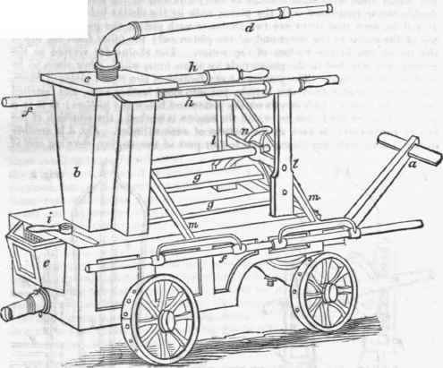
Fig. 2, in the subjoined engravings, is a section of the working parts of this engine through the cylinders, as seen on looking from the fore part of the cistern towards the air vessel; o o are the working cylinders or pump-barrels; p p the piston rods, with square holes to carry one end of the treadles; q is the double sector connected with the piston rods by the chains before mentioned. It will be seen that there are two chains to each piston, one passing from the top of the sector to the lower end of the piston rod; the other from the top of the piston rod to the bottom of the sector. The chains are riveted to the sectors, and attached to the piston rods by screw nuts, which allow them to be kept constantly tight. The pistons r r are formed of two round plates of brass, smaller in diameter than the barrels, put into stout leather cups, and fastened together by a nut, which screws on the piston-rod below the pistons; m m is a portion of one of the levers, by which the engine is worked; the situation of the two entrance-valves is seen at the bottom of each cylinder.
Continue to:


My Books

