


Boiler. Part 11
Description
This section is from the book "The Engineer's And Mechanic's Encyclopaedia", by Luke Hebert. Also available from Amazon: Engineer's And Mechanic's Encyclopaedia.
Boiler. Part 11
In the description of the common waggon-shaped boiler in the early part of this article, the manner usually adopted of feeding boilers with water was explained. The necessity of a due supply of the fluid is so great, as to have induced numerous inventors to devise plans for insuring its accomplishment.
Several of the most approved arrangements for this purpose are detailed in Galloway and Hebert's History of the Steam Engine; and we shall close the present article by the description of another of great simplicity and effectiveness, which was patented by Mr. W.Taylor of Wednesbury since the publication of the before-mentioned work. In the above figure, a shows a portion of the boiler; b a water reservoir or feeding vessel, made steam tight; c a pipe through which b is supplied with water, having a valve d opening inwards, e is a steam pipe, extending from the boiler to nearly the top of the close vessel b, and c is a water pipe extending from the bottom of the close vessel to the interior of the boiler. In both these pipes are stop cocks e and f, with levers extending to g, by which they are opened and closed. In these levers are two longitudinal slits, for the reception of a pin fixed in a rod extending from the float h, through a stuffing box in the top of the boiler. Now when the water in the boiler evaporates till its surface descends, and permits the weight of the float to bring down the levers to the position represented, the cocks will be opened, and the steam will rise through the pipe e, by which the pressure will be equalized in the boiler α and the supply vessel b, and water will descend through f till its surface in the boiler rises sufficiently high to raise the float and shut the valves; and then the condensation of steam in b will cause a partial vacuum, permitting a fresh dose of water to pass through c into the feed vessel.
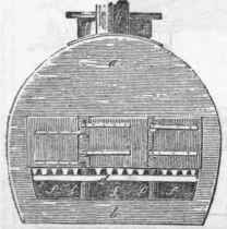
Fig. 1.
Fig. 2.
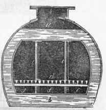
Fig. 3.
Continue to:


My Books

