


Boiler. Part 10
Description
This section is from the book "The Engineer's And Mechanic's Encyclopaedia", by Luke Hebert. Also available from Amazon: Engineer's And Mechanic's Encyclopaedia.
Boiler. Part 10
For the ready passage of the smoke, a temporary flue, which proceeds in a direct line to the chimney, is opened whilst lighting the fire, after which it is stopped by a damper or valve, which causes the current of heated matters to take the descending course described. By this arrangement, Mr. Gibbs extracts the gaseous products of the fuel, till they are reduced to nearly the temperature of cold water, the supply water being introduced where the flue terminates.
In the specification of this patent, Mr. Gibbs has also represented a long cylindrical boiler, placed horizontally, with three descending branches, and another with a flue in a zigzag direction, through the descending part of the boiler, which, although it has the advantage over the others of being of more easy manufacture, is not so favourable to the descent of the current. The partial action, owing to the unequal distribution of heat upon the different parts of a boiler, it was long since observed had a tendency to produce circulating currents of water throughout the vessel. This motion of the fluid has of late years been deemed of so much importance in the economical generation of steam, as to have induced several engineers to obtain patent privileges for their schemes: amongst these, Mr. Jacob Perkins is most conspicuous, for having taken out two patents for the same object, one in 1831, and the other in 1832. But as nature is inclined to perform the circulatory process pretty well without the assistance of art, we shall dismiss the subject with a brief notice of the above-mentioned gentleman's plans.
In the first of these, Mr. Perkins placed a thin metallic lining inside of the boiler, at a small distance from the bottom and sides, but leaving an opening in the lining at the bottom, where the heat of the fire is the strongest. Here, therefore, the water will acquire the greatest levity, and consequently ascend, while the water next to it, which is that between the lining and sides of the boiler, will occupy the bottom of the rising column, and thus a constant circulation will be kept up through the whole of the fluid in the vessel. In Mr. Perkins's second patent, which is stated to be for improvement on his former one, the aforesaid linings are to be augmented so as to cover a more extended surface, and form nearly a complete internal vessel at a few inches distance from the external one. It would require a large volume to describe the multiplicity of forms that have been introduced in the construction of boilers and their appendages, with the view of economising the production of steam. Those which we have already given, however, afford a general outline of the whole, with the exception of such as are employed in steam navigation.
In these, it is an essential condition that the fire-place and flues should be entirely surrounded with water, so as to prevent any contact of those parts with the wood-work of the vessel. We shall give two examples of boilers of this description.
Fig. 1
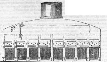
Fig. 2.
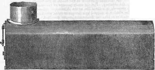
Fig. 3.
The above engraving is descriptive of the boiler used in the United Kingdom steam packet, of 1,000 tons burthen, measuring in her keel 148 feet, and breadth of beam 14 feet, and propelled by two engines of 100 horses each, manufactured by Mr. Napier, of Glasgow. The boiler is of wrought iron plates, 25 feet 6 inches long, 19 feet broad, and 8 feet 6 inches high. There are eight rectangular tubes b b running lengthways of the boiler; in each of these is a fire at one end on the bars c c, shown in section. At the farther end of the tubes is a transverse one d, extending the whole breadth of the boiler, which communicates with every one of the tubes containing the fire; at each end of d on the top, a return tube e e carries off the smoke and fire into another transverse tube f, out of the centre of which the chimney g rises. The cocks h h h are for ascertaining the height of the water in the boiler; but there is added a simple contrivance, by which the necessity of employing the cocks h is avoided.
There are two cocks i i which are placed the one considerably above, and the * her as much below, the assumed level of the water; these cocks communicate with a vertical tube of glass j of sufficient strength to withstand the force of the steam.
On the cocks i i being opened, water enters into the lower one, and steam into the upper one, and the pressure being the same in the boiler, the water stands at the same level in the glass tube, which indicates the height of the water in the boiler.
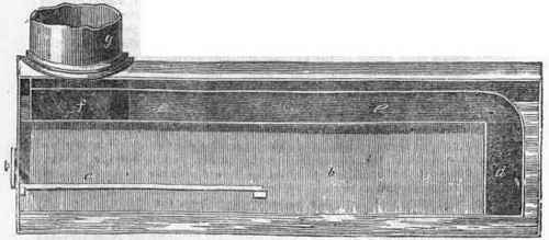
In the subjoined engraving, which represents a patented arrangement by Mr. Steenstrup, a Swedish gentleman, in this country, the boiler is divided into an upper and lower chamber, in connexion with the side chambers, and by means of vertical tubes. Fig. 1 is an end elevation of the boiler; Fig. 2 a transverse section; and Fig. 3 a longitudinal section, the same letters designating similar parts in each, a is the upper division, or steam chamber; b the lower chamber, connected with the upper by the side vessels, and by the vertical tubes c c, as shown in the section; at d, is the fire bars, on which the fuel is deposited; e the fire bridge; f the ash pit; g part of the chimney, likewise surrounded with water at the lower end, which is in contact with the vessel; h is the steam pipe, and k the man-hole. It will be observed that the vertical tubes c e besides forming a support to the weight of water in the upper chamber, and opening a free communication with it, receive, from their position in the fire-place, the strongest heat, and consequently give off steam quicker than the other parts of the boiler, in particular those which pass through the fire bars, producing thereby those ascending and descending currents, which are deemed so advantageous in the generation of steam: also, from the great capacity of the fire chamber, that fuel of any kind, however bulky, may be easily employed, by merely shifting the fire bridge accordingly.
Continue to:


My Books

