Setting Out Gradient Of Watercourse
Description
This section is from the book "Cassell's Cyclopaedia Of Mechanics", by Paul N. Hasluck. Also available from Amazon: Cassell's Cyclopaedia Of Mechanics.
Setting Out Gradient Of Watercourse
Below are given instructions on setting out with an ordinary spirit level a new watercourse. Make a straightedge of wood, say 9 ft. or 10 ft. long, 6 in. broad, and 1 in. thick (see A, Fig. 1), and true up one edge accurately. Some kind of supports will be required to carry the straightedge at a convenient height for sighting along; for this purpose, a couple of roughly made light trestles (see B, Fig. 1) will do. Cleats nailed on top of each trestle make a slot into which the straightedge may be placed with its true edge upwards. Wedges are placed under one end until the spirit level, when placed in the middle of the length of the straightedge, indicates that it is level, and by looking along its top edge a horizontal line may be sighted with a fair degree of accuracy. Fig. 1 shows the arrangement. The total tall in the full length of the proposed watercourse should be ascertained in the following manner. Set up the levelled straightedge at the top of the course, as at A (Fig. 2), directing it along the intended course. Send a man along as far as can be conveniently seen, say to the point B,and let him hold up a staff perpendicularly, and m front of it a piece of white paper, such as an envelope. The man at the level, by signalling, directs the man at the staff to raise or lower the paper until the top of it is exactly in a line with the edge of the straightedge. It the -tail' is not graduated in feet and inches, a pencil mark may be made and the height of the mark from the ground measured. Supposing the height of the straightedge from the ground at A (Fig. 2) is 3ft., and the height sighted on the staff at B is 1ft. 9in..there is a fall of 1 ft. 9 in. in the surface between these two points. The straightedge is now shifted to B, and a further sight taken towards C in the same manner, and so on until the whole course has been traversed. The sum of the whole of the falls, less any rises there may be, will give the total fall available. Suppose the fall to be 2 ft. 3 in. in a total length of 900ft.: this is equivalent to 1ft. of fall in 400 ft., or lin. of fall in 400 in., or 33 ft. 4 in. To set out this gradient on the ground, so as to cut the new watercourse to an even fall, it is advisable to have sight rails put up at distances of 100 yd. or 150 yd. apart. Sight rails are an arrangement of two uprights and a horizontal cross-piece spanning the line of the excavation in the manner shown in Fig. 3, and they are used m conjunction with a loose staff, called a boning rod, which has a small cross-head at the top. Supposing the depth of the excavation to be, for the most part, about 3 ft a convenient length for the boning rod will be 6 ft., so that the sight rails will be approximately 3 ft. above the level of the ground. The first sight rail will be fixed at the height of the boning rod, i.e. 6 ft., over the starting point of the watercourse. Now, with a gradient of 1 in 400, if the second sight rail be fixed 100yd. along the line, it will require to be 9in. lower than the first one; tor 100 yd. equals 300 ft., and if the fall in 400ft. is lft., the fall in 300 ft. will be 9 in. To get the correct height tor the second sight rail, fix up the levelled straightedge immediately underneath the first sight rail, measuring with a rule how much it is below the top edge of the si°-ht rail. Suppose the measurement is 14m. Let the man with the staff mark the height of the horizontal sight line as before, and it is evident that the height so marked will be 14 in. below the first sight rail; and as the second sight rail has to be 9in. lower than the first, then 5 in. above the point marked on the staff will be the right height at which to fix the rail.
When the sight rails have been put in in this way, the boning rod is used to try the level of the bottom of the cutting, as shown in Fig. 3. If the cutting is at the right depth, the tops of the sight rails and of the boning rod will be all in one line.
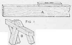
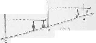
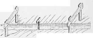
Fig. 3. Setting Out Gradient of Watercourse.
Continue to:
My Books

