Dressing Up Spokes Of Carriage Wheels
Description
This section is from the book "Cassell's Cyclopaedia Of Mechanics", by Paul N. Hasluck. Also available from Amazon: Cassell's Cyclopaedia Of Mechanics.
Dressing Up Spokes Of Carriage Wheels
An easily made apparatus that will hold the spokes of wheels whilst dressing them up is illustrated by Fig. 1, which is a side view showing a spoke in position. The bottom rail A is 1 3/4 in. deep by 1 1/2 in. thick, shouldered in at B to 1 in. thick. On this part the block C works along by the mortise shown in Fig. 2, being kept in position by the wedge at the back D (Fig. 1). To" this block is fixed an iron plate (see Fig. 3), the lower part being 1 1/2 in. wide by 1/4 in. thick, the projecting centre-point being 5/8 in. round, welded into it. A pillar 1 1/2 in. square is mortised on the front end, being firmly fixed by a corner plate, as Fig. 4. This is made with a boss at the top to the full width of plate, 1 1/2 in., through which the 5/8 in. screw E is fitted. This has a handle fitted at the end, and when in use the frame is held in the vice, or may be cramped to the bench, and the block is slid along to about the length of the spoke. The latter is placed between the two centre-points, a turn or two of the screw holding the spoke firm, whilst it can also be turned round in any position for working.
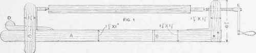
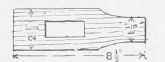
Fig. 2.


Apparatus for Holding Spokes of Wheels.
Continue to:
My Books

