A Tool-Holder For A Slide Rest
Description
This section is from the book "Cassell's Cyclopaedia Of Mechanics", by Paul N. Hasluck. Also available from Amazon: Cassell's Cyclopaedia Of Mechanics.
A Tool-Holder For A Slide Rest
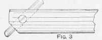
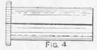
Figs. 1 and 2 show a very handy American tool-holder for slide-rests, with a tongue to fit into the T-slot in place of the regular tool post. It can very easily be constructed to fit an English slide-rest by leaving off the tongue and having it plaued flat on the bottom. In commencing to make it. the base of the iron casting being planed, the hole should be bored with a boring bar between the centres of the lathe with which the holder is to be used. A 3/4-in. hole is about right for a 4 1/2-in. centre lathe. The slot A (Figs. 1 and 2) is cut with a hack-saw, and clamping screws are shown at B. The dotted lines at C indicate the bolt hole for fastening the holder to the slide-rest. Fig. 3 shows a 3/4-in. steel boring bar, which should have a total length of about 10 in. A 1/4-ia. tapped hole carries a grub screw, and a corner of the bar is filed off. The hole for the cutter should be drilled, the cutter being of 3/16-in. square tool steel. Fig. 4 shows a split bush to hold a 1/2,-in. bar; it has a milled end to facilitate removal. Several such bushes should be made to accommodate a variety of bars, and also one or more with the holes eccentric to the centre of the bushing to hold small steel. By that means it is easy to place the cutting point of the tool at any height required.
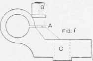
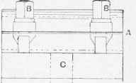
Fig. 2.
Tool-holder for a Slide-rest.
Continue to:
My Books

