A Model Pumping Windmill
Description
This section is from the book "Cassell's Cyclopaedia Of Mechanics", by Paul N. Hasluck. Also available from Amazon: Cassell's Cyclopaedia Of Mechanics.
A Model Pumping Windmill
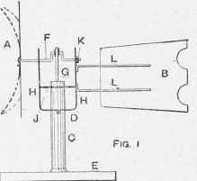
The little windmill here described is easily made, and works well in quite a moderate wind. It may be made in any size, even with the wheel Jin. in diameter, but the one illustrated has a 1-in. wheel, and the drawings are quarter full size. For larger or smaller mills, all the parts may be kept in about the same proportion. The wheel A (Fig. 1) and rudder B are best made of thin sheet brass, but tin-plate is found quite suitable if it is painted. For the wheel, strike a circle 4 in. in diameter, and a smaller one 3/4 in. in diameter, and concentric. Then divide the disc into eight sections (see Fig. 2), either by using set-squares, or by dividing the circle into two parts and stepping the compass,s four times round each semicircle; a;. -in. hole is bored in the centre of the circle, and it is then carefully cut out with a pair of shears. Afterwards the eight radiating lines are cut down, as shown, to the inner circle; all sharp corners are then snipped off and trimmed with a tile. The rudder B (Fig. 1) is about 3 in. long and 2 1/2n. and 2 in. wide at the large and small ends respectively, and it should be trued up at the edges with a file. The pump barrel C is a brass tube about 4 in. in diameter and 3in. long. With a file the ends are trimmed square to the length. A small hole is bored through the tube at D about lin. from one end, and a little plug of iron or brass wire is soldered or forced in, leaving 1/4in. protruding at each side, the ends being rounded. The stand E is either a heavy sheet-iron plate 4in. by 4 in. by /4in., or a light metal one screwed to a wood base; on it, at the centre, the pump is soldered upright. The crank-shaft F is made from steel or iron wire about ft in. in diameter and 3 1/2 in. long. The crank is made by heating the metal red hot and bending it with a pair of pliers or in a small vice; the throw of the crank should not be more than Jin. The pump rod G is made of thin brass or iron wire about 2in. Ions, and one end is bent over into a circle to tit loosely on the crank-shaft. The frame is of brass 5 1/2 in. by 3/4in. by 1/16 in., and is bent as shown at H. To bend brass or copper,it is annealed by heating it to red heat and cooling it suddenly in cold water, after which it bends easily and without breaking.
A hole is bored in the bottom to fit the tube C; also one at each side at the top to take the crank-shaft. A second piece of brass J is cut about 1 1/4 in. by 3/4iu. by 1/16 in., and a central hole is bored in this to fit the pump barrel. The piece is now soldered about 1 in. up the frame. The wheel A is soldered true to the shaft, and about 3/4 in. out from the front bearing, the space being filled with a washer made by coiling some No. 18 S.W.6. copper wire round the shaft, the ends being filed so as not to catch anywhere. The wheel and shaft are now put into the bearings, the latter being sprung if necessary. The pi'otruding ends are sawn or filed off, and a washer K.made of No. 16 S.W.G. copper, is soldered on. The pump rod G is put in place, and two small copper wire washers are soldered on the crank-pin to prevent the rod having too much side play. The lower end of the pump rod must be cut shorter if it does not allow the crank-shaft to rotate freely. The rudder is soldered to two brass wires L about 3 in. long, and these are soldered to the frame. Finally, each blade or section of the wheel is given a twist as in a screw propeller or fan, and as indicated for two sections. "When the mill is running, the vane or rudder should keep it well into the wind.
All iron or tin parts should be painted, and the bearings oiled. The holes can be bored with common bradawls sharpened like an ordinary metal drill, and the larger holes may be finished with a round file. All parts to be soldered should be very clean, zinc chloride being used as the flux.
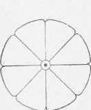
Fig. 2.
A Model Pumping Windmill.
Continue to:
My Books

