Treatment Of Crossheads
Description
This section is from the book "The Mechanician, A Treatise On The Construction And Manipulation Of Tools", by Cameron Knight. Also available from Amazon: The mechanician: A treatise on the construction and manipulation of tools.
Treatment Of Crossheads
There are three principal sorts of crossheads, - comprising the old crosshead having two comparative broad flat arms, the crosshead which is circular and is shaped entirely with lathe-turning, and the two piston-rod crosshead employed in marine engines.
Lining And Centring Of Crossheads
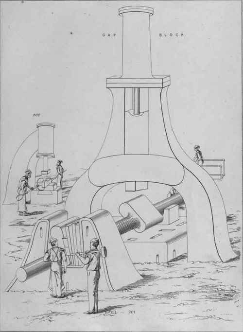
At the conclusion of a crosshead's forging, it should be carefully straightened while yet in the smithy, by means of a large anvil or table situate beneath a steam hammer, such as the table shown in Plate 19. While on the table the crosshead is supported on iron or steel packing blocks; these are put beneath each arm, and are situate, either near the boss in the middle, or near the two pivot-ends, according to whether the arms are bent near these ends, or bent near the boss. After being properly straightened and made about equally soft along its entire length, by being equally heated and allowed slowly to cool, the article is ready to be lined and centred for lathe-turning.
Plate 19
However large the crosshead may be, or however much superfluous metal it may possess to be cut off, it should be turned previous to being planed; unless it happens to be a two piston-rod crosshead, in which case, the planing should be done previously to the turning.
To perform the lining, the object is put upon a lining-table of suitable dimensions, and scribed with the scriber-block, which rests on the table. During this operation it is situate with parallel blocks in contact with its two arms, as indicated in Fig. 1110; and while on these blocks it is adjusted to parallelism with the table. To do this, a few arcs are marked upon the narrow sides or edges with a calliper, in order to find the centres of a few places along the surfaces. In Fig. 1111 such marks are seen, each set of marks consisting of a couple of arcs having a short straight line midway between. Both edges of the crosshead are thus marked, the short centre lines being easily scratched with a scriber as soon as the arcs are made with a calliper, in fact, a mere dot with a dotter is sufficient. The dots or centre marks thus obtained, represent a few points in a sort of primary line extending entirely around the crosshead; and constitute points which are to be put at about one height from the table, which is done by placing packing-pieces and wedges of proper thickness beneath the arms, and by referring to the point of the scriber-block standing on the table.
As soon as all the centre-marks are put as nearly parallel to the table as their relative situations will admit, the crosshead's broad sides are, by the same act, put parallel with the table, supposing that they are parallel with each other; but if not, both the upper sides, and the lower sides, are equally inclined to the table, in consequence of the centre of both narrow sides having been found, and adjusted to the scriber-point. The crosshead is, therefore, in position for partly scribing the centres for turning, and the point of the block's scriber is next adjusted to the mean height of all the centre-dots, and then placed to scribe a short straight line upon the outer extremity of each pivot-end. In Fig. 1110 one of these lines is seen, and the places for the desired centre-recesses are partly indicated.
The centres being now marked, with regard to the narrow sides, it is next necessary to indicate the centres with regard to the broad sides. For this purpose, the crosshead is lifted and stood edgeways upon the table. At the second placing, it is not requisite to adjust either of the broad sides exactly square to the table, or square to the previous situation of the crosshead; but it is requisite to place the centre length of the broad sides parallel with the table, that the axis on which the crosshead will rotate, may be in line with the centre length. Callipers are therefore used, as before, to scribe a few couples of arcs, which are shown on the broad side in Fig. 1112, a dot being put between each two arcs to mark the centre length. These dots are used in the same way as those on the narrow side, the point of the scriber being adjusted to the mean height of all the dots, as soon as both ends of the crosshead are put equidistant from the table. By now scribing a short line upon each outer extremity of the pivot-end, causing them to intersect the two lines marked at the previous scribing, a couple of crosses are delineated, one of which is denoted in Fig. 1113. A dot is now put into the centre of each cross, which indicates the exact places for the desired conical recesses.
The mode of centring just given, is suitable for any crosshead which is so forged as to possess the usual amount of superfluous metal on the pivot-ends. By centring the object with regard to the arms, it is presumed that these are the portions having the least amount of metal to be cut off; but if it happens that the pivot-ends and the middle boss have but little extra metal, these must be considered in preference to the arms. The lining, in this case is, therefore, performed by placing vee-blocks beneath the ends, instead of placing flat blocks and wedges beneath the arms. When vee-blocks are used, the finding of centres along the arms with a calliper, and adjusting the scriber-block thereto, is dispensed with ; but it is necessary to find the centre of each face of the middle boss, with a calliper, and to adjust the scriber-point either to these centres or to those shown by rotating and reversing the crosshead on the blocks. To ascertain which of these are to be regarded, the operator discovers, as in other cases, which portion is forged nearest to the desired size.
The first centring of a circular crosshead is, in any case, effected with vee-blocks. The blocks are put beneath those portions which are somewhat nearer to the specified dimensions than the other portions; and because the boss in the middle, and the junctions of the arms, are the parts which should be nearest to the intended diameters, the vee-blocks should be in contact with such parts, as indicated in Fig. 1114. This will cause the centres to be scribed without regard to the ends, which have an abundance of metal, and which can be much easier turned than the mid-portion.
Continue to:
My Books

