Connecting-Rods With T-Ends And Fork-Ends
Description
This section is from the book "The Mechanician, A Treatise On The Construction And Manipulation Of Tools", by Cameron Knight. Also available from Amazon: The mechanician: A treatise on the construction and manipulation of tools.
Connecting-Rods With T-Ends And Fork-Ends
Connecting-rods are of three principal varieties, the simplest form of these being the rod with two T-ends; the next class having hollow or curved ends for circular brasses; and the third variety having a T at one end, and at the other a fork.
Plate 13
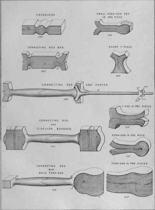
Plate 13 represents the several classes of rods in their respective shapes during forging. In this Plate, Fig. 144 represents a small connecting-rod in process of forging from one straight bar. Fig. 145 indicates a connecting-rod with two T-ends, also in one bar. Fig. 146 shows a similar sort of rod, but made of two pieces. Fig. 147 points out a connecting-rod intended to have hollow ends for circular brasses. Fig. 148 denotes a rod having a fork at one end, and at the other a T-end, which is at right angles to the fork; or, in lengthy language, at right angles to a line through the centres of the two fork-eyes that are intended to contain the connecting-pin, gudgeon, or gudgeon-crosshead.
Small connecting-rods with fork-ends are sometimes made without a T-portion at the other end. Instead of a T-end, a screw is used, or key inserted. For such a rod the bar of which the work is to be made requires to be split open at one end only, to produce the fork. To make a rod with both fork-end and T-end, the bar is split at both ends ; then opened and shaped to the desired form. By these considerations it may be inferred that a tough tenacious iron is necessary, if only the forging of the rod be considered. If brittle Bessemer iron be selected, it is troublesome to make either a T or a fork, without great risk of cracking and spoiling the work during its forging. The smith will therefore select the iron with due regard to its capability of being forged, and to its durability afterwards.
The convenient mode of forging a small rod, shown by Fig. 144, consists in making the T-end first, because of the upsetting which is needed. If a very small rod, a slit is cut at one end of a bar whose length is convenient for handling, and the two ends thus formed are opened until the T-piece is produced. A welding heat and upsetting is then necessary to thoroughly flatten the extremity, and to erase the appearance of the split. Larger rods may need a hole to be punched, previous to cutting the slit; the hole allowing the ends to be easily spread out and flattened to a right angle. After the T-end is thus shaped, the necessary length of iron is ascertained, when the work is cut from the bar and the fork-end produced.
The manner of splitting the bar for the fork depends upon the thickness. A small bar is divided by a chisel-cut only ; a larger bar needs a hole to be punched, and a slit cut from the hole to the extremity; a still larger bar may require two chisel-slits from the hole, so that a piece may be cut entirely out, to shorten the after process of thinning the fork-ends, after the slit or opening is made.
After the opening is made, the curving and shaping of the intended fork is effected by first hammering the work while on a round filler of suitable diameter, which is across a pair of blocks as shown by Fig. 142. The fork being very small, a piece of round iron half an inch in diameter may be large enough.
A pair of small fullers are next driven in to form the hollows that adjoin the circular portions, in the middle of which are the holes or eyes for the gudgeon, or gudgeon crosshead.
The final flattening of the fork-gap is effected by hammering the fork-ends while on the edge of a flat bar, which is in the gaps of the blocks that previously supported a round bar.
In those cases that require a large number of such small fork-ends to be finished on the anvil, it is necessary to make a steel filler which is just the thickness of the intended gap; one side of the filler, or what is named one edge of it, being curved to shape the bottom of the gap. This filler is held in the fork-gap by a gap-stop, while the outsides are hammered to make the insides of correct dimensions. A gap-stop in the square hole of an anvil is shown by Fig. 77.
When the fork-end and T-end are made, the intermediate part of the rod is drawn down and the length increased to the length desired.
Figure 145 indicates a connecting-rod bar which is split at each end, and also fullered at the inner sides of the intended T-portions. To make a T-end rod in such a manner of one piece, the bar at the commencement of the forging may be equal in diameter to about two-thirds of the entire length of the intended T-end. A short slit, S, is first cut to allow the ends of the bar to be spread to the desired length of the T-part. Fullers are next driven in to produce the hollows or recesses indicated by H. The thick lump in the middle is then reduced by steam-hammering to the desired diameter and length.
Rods with two T-ends are also made of two pieces, as shown by Figure 146 ; this mode being adopted for portability, or for the purpose of using two short pieces of iron when one piece of sufficient length is not comatable.
Reference to the Figure (146) will show that each piece has a slit at one end, corresponding to the two slits in Fig. 145. The utility of these openings is rendered apparent, by considering the economy of iron resulting from opening the end, instead of reducing the rod from a bar which is as thick as the length of the intended T or head; also by considering the proper disposition or arrangement of the fibres in the T-pieces. At all times when circumstances permit, the forging should be so managed as to place the lengths of the fibres in the two heads at right angles to the length of the rod itself.
To obtain this arrangement, it is only necessary to cut open the ends and upset the work as indicated by the Figures - the ordinary method of upsetting heavy work being by the pendulum-hammer ; and, in a few cases, with a steam-hammer. Although it is not convenient to upset work of great length by a steam-hammer, it may be conveniently used for a short piece which has a base or bottom of sufficient dimension to maintain the work in an upright position during the hammering. Pieces not exceeding two or three feet in height may be managed with an ordinary steam-hammer by driving a fuller into the middle of a short piece, as shown by Fig. 149, after which the two prominent portions are driven down by the hammer and at the same time spread out to form the head, or what is named the T. For this purpose, a hammer should be used whose face is concave, and not flat.
Continue to:
My Books

