Fractional Separation Of The Naphthas And Light Oils. Part 4
Description
This section is from the book "Distillation Principles And Processes", by Sydney Young. Also available from Amazon: Distillation Principles And Processes.
Fractional Separation Of The Naphthas And Light Oils. Part 4
(A) Packed Columns
The earliest types of columns consisted of a cylinder of wrought or cast iron in which are promiscuously thrown bricks, stones, or any material that will break up the vapours and so cause intimate contact between them and the condensed liquid ; such a crude type of plant was patented by B. Hoff (Eng. Pat. 3468, 1889).
Raschig's Ring Still
F. Raschig (Eng. Pat. 6288, 1914; and Ger. Pats. 286122, 1915 ; 292622, 1916 ; 297379 and 298131, 1917) further developed the idea of packing columns by employing his rings ; to which reference has been made in a previous chapter. These rings are pieces of thin-walled piping, the length and diameter of which are equal. They are thrown into the column and allowed to arrange themselves promiscuously just as they fall into position. A very uniform distribution is thus obtained which does not tend to assist the formation of particular channels for the vapours. The rings should be of such a size (25 mm.) that not less than 55,000 go to a cubic metre. The surface exposed per cubic metre of volume with such a filling amounts to about 300 square metres. Further, as little as 10 to 20 per cent only of the volume is actually occupied by the material of the rings. The column, moreover, offers little resistance to the vapours, e.g. a column 10 metres high and of 1 square metre cross-section will pass 500 cubic metres of vapour per hour under a pressure of only 2 mm of water.
1 Rosanoff and Bacon, J. Amer. Chem. Soc., 1915, 37, 301.
One of the chief points claimed in Raschig's Patent is the irregular arrangement of the rings in the column, whereby both vapour and liquid in their passage are compelled to change their direction so frequently that their intimate and frequently repeated contact is assured.

Fig. 164.-Raschig Rings.
Other Packed Stills
Modified forms of packing rings have been devised by Goodwin (Eng. Pat. 110260, 1917), Lessing (Eng. Pat.

Fig. 165. - Lessing Rings.
139880, 1920), and Prym (Ger. Pats. 317166 and 317167). Somewhat similar hollow balls and cellular bodies were described by Guttmann (Eng. Pats. 14774, 1896 ; and 4407, 1907).
Goodwin's rings consist of "units constructed or shaped in the fashion of two hollow truncated circular cones, united at their smaller diameter, at which part both the interior and the exterior junction points are rounded and smoothed off, leaving a unit substantially the same external shape and internal section as a dice-throwing box, but, of course, open at both top and bottom" (Fig. 166).
Such rings are filled into a fractionating column either regularly or irregularly. The vapours in passing through this filling are constantly throttled and allowed to expand, their velocities being thereby alternately increased and decreased with the resultant formation of eddies which ensure efficient contact between vapour and liquid,
Lessing's and Prym's rings differ from others in having "a more or less central partition," in consequence of which they offer a larger surface without materially increased obstruction to the passage of the vapour and liquid" (Fig. 166).
Packed columns are convenient in some respects in that they are cheap and easy to erect and the rings are very light. They fail, however, in one particular as they do not regularly bring vapour and liquid together. It stands to reason that where the packing is promiscuous the ascending vapour will go by the passage giving the least resistance. Again, the descending liquid will come down the channel of least resistance. It may easily happen that these two passages are not the same, so that regular and intimate contact is not assured. This so-called "channelling" is more marked when the column has been used for some time and is dirty, and chiefly in this fact lies the alleged improvement in using the various kinds of rings described instead of such articles as brickbats.
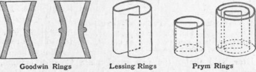
Fig. 166.
Packed 'columns can well be used for crude distillation, but the tendency to channelling makes them of little use for intensive fractionation compared, at any rate, with the more modern cup and seal column.
(B) Perforated Plate Columns
This column (Fig. 167) is simple in construction and is composed of a cylinder of the required height containing horizontal partitions throughout the whole length. The partitions are bored over the whole surface with small holes. The number and size of holes are variable and made according to the rate at which the still is required to be worked. They must be of small enough area to keep a certain quantity of liquid on each tray so that the ascending vapour continuously bubbles through this liquor. The earlier inventors of this class of columns were Coffey and Savalle.
In the actual working of a perforated plate column difficulties arise, for if the still is run faster than the rate for which the holes are designed, the sections begin to fill up; while on the other hand, if it is worked too slowly the whole column drains down, leaving no liquid on the plates. This difficulty was partially got over by inserting overflow pipes in each tray, the upper end of each pipe protruding some few inches above the level of the plate. Each tray was supplied with one overflow pipe which dipped into the liquid on the tray below it, this tray having its overflow on the opposite side of the column. Thus the returning liquid had to traverse a zigzag course on its way down the column. D Savalle et Fils, of Paris,1 erected such an apparatus and obtained good results. Many distillers, as seen later, still prefer the perforated plate type of column, and maintain that it gives as good results as the cup and seal column. In the opinion and experience of the author they are not so good in practice. To carry out efficiently a separation by fractionation it is necessary to alter the rate of working frequently, and with any kind of perforated plate column it is impossible to slow the still down to a lower speed than the area of the holes will allow, otherwise the plates will drain. The only method of overcoming this difficulty is to reduce the hole area, but the still cannot then be worked at high speed without getting an abnormal amount of pressure on the column. From this it will be seen that the flexibility of any individual column is not large, and it must be worked at a certain limited range of speed to attain the best results. In most cases it will be found that great difficulty is experienced to obtain a constant pressure in the steam boiler, so that varying temperatures are obtained in the heating coils of the still. This naturally tends to vary slightly the speed of flow of distillate and is fatal to a column, such as the one described, that is so sensitive to changes of speed. This trouble can be overcome by introducing a reducing valve before the steam enters the still, but only at a big expense of fuel. Again, if the column is erected in the open it must be covered, otherwise winds, rain and other atmospheric conditions very quickly alter the amount of condensation in the column.

1 Bulletin de la Sociele d'Encouragement, 1876, p. 657; Dingl. pdyt. J. 223, p. 615.
Fig. 167.
A, fixed plate ; B, ascending vapour pipe ; C, hood, dome, or cup ; D, return pipe.
Continue to:
My Books

