History Of Bridge Building. Part 2
Description
This section is from "The Encyclopaedia Britannica". Also available from Amazon: Great Books of the Western World (60 Volumes).
History Of Bridge Building. Part 2
Down to 1850 such bridges were generally limited to 150 ft. span. The timber was white pine. As railway loads increased and greater spans were demanded, the Howe truss was stiffened by timber arches on each side of each girder. Such a composite structure is, however, fundamentally defective, the distribution of loading to the two independent systems being indeterminate. Remarkably high timber piers were built. The Genesee viaduct, 800 ft. in length, built in 1851-1852 in 10 spans, had timber trestle piers 190 ft. in height. (See Mosse, "American Timber Bridges," Proc. Inst. C.E. xxii. p. 305, and for more modern examples, cxlii. p. 409; and clv. p. 382; Cooper, "American Railroad Bridges," Trans. Am. Soc. C.E. vol. xxi pp. 1-28.) These timber framed structures served as models for the earlier metal trusses which began to be used soon after 1850, and which, except in a few localities where iron is costly, have quite superseded them.
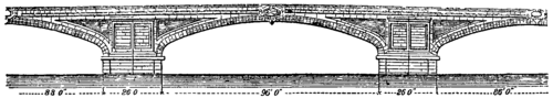 Fig. 7. - Ponte della Trinità, Florence.
7. (b) Masonry. - The present London Bridge, begun in 1824 and completed in 1831, is as fine an example of a masonry arch structure as can be found (figs. 8 and 9). The design was made by John Rennie the elder, and the acting engineer was his son, Sir John Rennie. The semi-elliptical shape of the arches the variation of span, the slight curvature of the roadway, and the simple yet bold architectural details, combine to make it a singularly beautiful bridge. The centre arch has a span of 152 ft., and rises 29 ft. 6 in above Trinity high-water mark; the arches on each side of the centre have a span of 140 ft. and the abutment arches 130 ft. The total length of the bridge is 1005 ft., its width from outside to outside 56 ft., and height above low water 60 ft. The two centre piers are 24 ft. thick, the exterior stones are granite, the interior, half Bramley Fall and half from Painshaw, Derbyshire. The voussoirs of the centre arch (all of granite) are 4 ft. 9 in. deep at the crown, and increase to not less than 9 ft. at the springing. The general depth at which the foundations are laid is about 29 ft. 6 in. below low water.
The total cost was £1,458,311, but the contractor's tender for the bridge alone was £425,081.
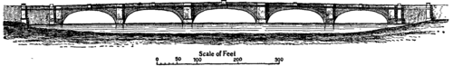 Fig. 8. - London New Bridge.
Since 1867 it had been recognized that London Bridge was inadequate to carry the traffic passing over it, and a scheme for widening it was adopted in 1900. This was carried out in 1902-1904, the footways being carried on granite corbels, on which are mounted cornices and open parapets. The width between parapets is now 65 ft., giving a roadway of 35 ft. and two footways of 15 ft. each. The architect was Andrew Murray and the engineer, G. E. W. Cruttwell. (Cole, Proc. Inst. C.E. clxi. p. 290.)
The largest masonry arch is the Adolphe bridge in Luxemburg, erected in 1900-1903. This has a span of 278 ft., 138 ft. rise above the river, and 102 ft. from foundation to crown. The thickness of the arch is 4 ft. 8 in. at the crown and 7 ft. 2 in. where it joins the spandrel masonry. The roadway is 52 ft. 6 in. wide. The bridge is not continuous in width, there are arch rings on each face, each 16.4 ft. wide with a space between of 19.7 ft. This space is filled with a flooring of reinforced concrete, resting on the two arches, and carrying the central roadway. By the method adopted the total masonry has been reduced one-third. One centering was used for the two arch rings, supported on dwarf walls which formed a slipway, along which it was moved after the first was built.
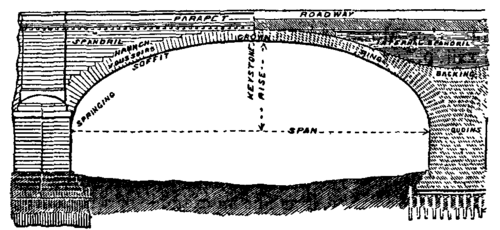 Fig. 9. - Half Elevation and Half Section of Arch of London Bridge.
Till near the end of the 19th century bridges of masonry or brickwork were so constructed that they had to be treated as rigid blockwork structures. The stability of such structures depends on the position of the line of pressure relatively to the intrados and extrados of the arch ring. Generally, so far as could be ascertained, the line of pressure lies within the middle half of the depth of the voussoirs. In finding the abutment reactions some principle such as the principle of least action must be used, and some assumptions of doubtful validity made. But if hinges are introduced at crown and springings, the calculation of the stresses in the arch ring becomes simple, as the line of pressures must pass through the hinges. Such hinges have been used not only for metal arches, but in a modified form for masonry and concrete arches. Three cases therefore arise: (a) The arch is rigid at crown and springings; (b) the arch is two-hinged (hinges at springings); (c) the arch is three-hinged (hinges at crown and springings). For an elementary account of the theory of arches, hinged or not, reference may be made to a paper by H. M. Martin (Proc. Inst. C. E. vol. xciii. p. 462); and for that of the elastic arch, to a paper by A.E.Young (Proc. Inst. C.E. vol. cxxxi. p. 323).
In Germany and America two- and three-hinged arches of masonry and concrete have been built, up to 150 ft. span, with much economy, and the calculations being simple, an engineer can venture to work closely to the dimensions required by theory. For hinges, Leibbrand, of Stuttgart, uses sheets of lead about 1 in. thick extending over the middle third of the depth of the voussoir joints, the rest of the joints being left open. As the lead is plastic this construction is virtually an articulation. If the pressure on the lead is uniformly varying, the centre of pressure must be within the middle third of the width of the lead; that is, it cannot deviate from the centre of the voussoir joint by more than one-eighteenth of its depth. In any case the position of the line of pressures is confined at the lead articulations within very narrow limits, and ambiguity as to the stresses is greatly diminished. The restricted area on which the pressure acts at the lead joints involves greater intensity of stress than has been usual in arched bridges.
Continue to:
My Books

