


Turret Lathes. Part 3
Description
This section is from the book "Machine Shop Work", by Frederick W. Turner, Oscar E. Perrigo, Howard P. Fairfield. Also available from Amazon: Machine shop work.
Turret Lathes. Part 3
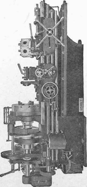
Fig. 297. "I" 24-Inch Turret Lathe with Motor Drive Courtesy of Gisholt Machine Company, Madison, Wisconsin.
A very complete turret lathe is shown in Fig. 297, as an example of class 5. The turret is mounted upon a carriage fitted to the V's of the bed, and provided with an apron carrying the feeding mechanism. The turret is not set upon, a horizontal support and pivoted on a vertical stud, as in the former examples, but it is inclined toward the back of the machine for the purpose of elevating the long turret tools out of the way of the operator. The turret is hexagonal, and the faces drilled and reamed for holding cylindrical shanked tools, and also accurately faced, drilled, and tapped for bolting on large and heavy special tools and devices. The turret is revolved automatically, and the cutting movement is controlled and limited by individual adjustable stops for each turret tool. The lateral movement of the turret is produced by a lead screw of very sharp pitch, so that the return stroke is not only automatic but rapid. Upon a heavy carriage, designed upon the lines of a heavy engine lathe carriage, is mounted a revolving tool-post adapted to carry four tools for cutting-off, forming, turning, etc. A taper-turning attachment is located at the rear of the carriage, whereby tapered work may be as readily turned as straight work. The lateral movement of the carriage is controlled and limited by four adjustable stops at the left, thus providing individual stops for the tool-post tools. Stops are also provided for their transverse cuts. A system of piping is provided, whereby all tools may be lubricated by oil or other lubricant, under pressure from a rotary oil-pump. This form of lathe is built very substantially, and is intended for the machining of large and heavy castings. For this purpose the turret as well as the carriage is equipped with long and heavy tools, some of which will be illustrated and described later on. The headstock of this lathe is very large and substantially built, and is triple-geared so as to give it great driving power for heavy work. It is driven by an electric motor, the rheostat for which is seen at the extreme left of the engraving, near the floor. In Fig. 298 is shown an automatic turret lathe built by the Reed-Prentice Company of Worcester, Massachusetts.
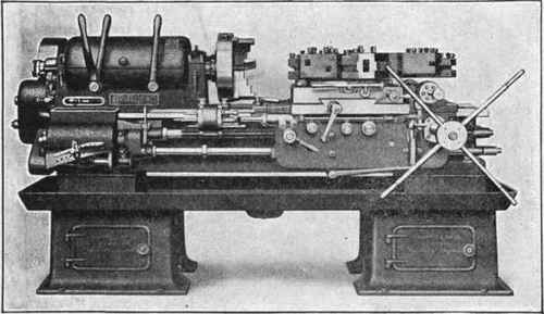
Fig. 298. "Prentice" High-Speed Turret Lathe Courtesy of Reed-Prentice Company, Worcester, Massachusetts.
Fig. 299 shows what is known as the flat turret lathe, so called from the design of the turret. In this case the tools are not placed in tool holes in the outside of the turret nor bolted to the faces of it. On the contrary, they are bolted down to the upper surface of a horizontal, circular plate. It is a radical and most successful innovation in the designing of a turret lathe, and requires tools and fixtures specially designed for its use.
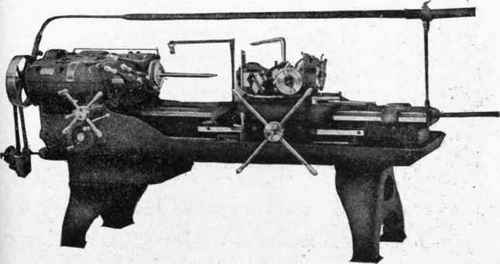
Fig. 299. Flat Turret Lathe, with Special Tools Bolted to Top of Flat Plate Courtesy of Jones and Lamson, Springfield, Vermont.
In other examples we have what is called the hollow hexagonal turret, which, instead of being made solid as in Fig. 293 and numerous other examples, consists of walls of sufficient thickness to properly support the tool-holders and the tools bolted to it.
Turret-Lathe Tools, A great variety of tools are used in the turret lathe, for an indefinite number of uses, as the different forms of pieces to be machined are of a never-ending variety of shapes which almost defies any attempt at analysis or classification. It is possible, however, in a general way, to separate these tools according to the work which they are designed to do, as follows:
(1) For the Turret: Centering tools, drills, reamers, counterbores. For the Cross-Slide: Cutting-off tools and plain forming tools, as for finishing the end of the bar after a machined piece is cut off, cutting a groove in the work before it is cut off, etc.
(2) For the Turret: Plain box tools containing a turning tool and a back rest, both adjustable to different diameters; taps and threading dies and holders for the same; forming tools that may be run on the end of a cylindrical piece of work. For the Cross-Slide: In addition to the cutting-tools, horizontally moving and vertically moving forming tools. (Occasionally these tools may be so made as to move in an inclined direction.)
(3) For the Turret: Box tools carrying several turning or forming tools, or both, with the necessary back rests, bushings, etc. For the Cross-
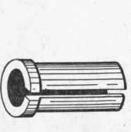
Fig. 300. Split Collet.
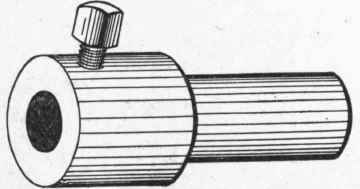
Fig. 301. Plain Drill Holder.
Slide: Facing tools; multiple tool-holders, carrying, turning, cutting-off, and forming tools, and special tool-posts.
(4) This class includes a large number of special tools and fixtures for use in both the turret and cross-slide, by which a great variety of work of all sizes and forms is successfully machined.
Continue to:


My Books

